
← Back To Portfolio VT-PLN / BEEST LOG

Hack Club BEEST

Little Helper Devlog

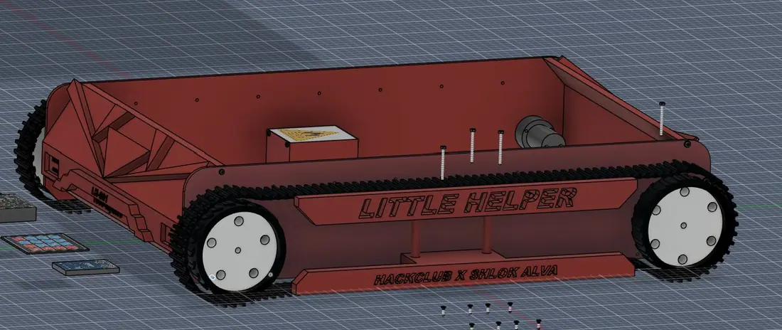
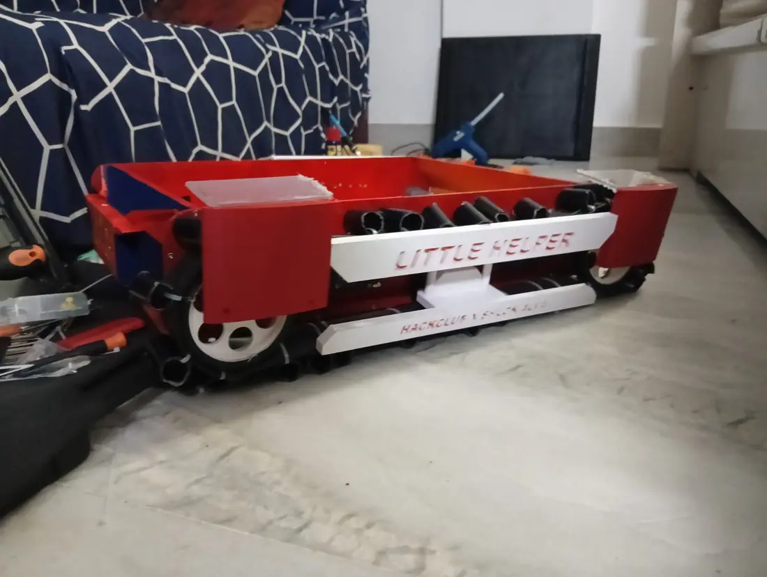
Little Helper is my track-based 4WD robot that carries books and papers for teachers. It was my Hack Club BEEST project, and it had to be shipped to Hack Club’s standards. This is the full log, in order.

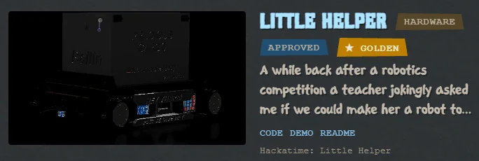
The Little Helper project card on Hack Club BEEST, marked Hardware, Approved and Golden
Devlogs
70
First entry
May 31, 2026
Last entry
Aug 19, 2026
Status
Approved, Golden

The Shipping Standards

twin this is like amazing congratulations on such a cool project (and thank you for not submitting slop from the review team)

Hack Club reviewer, Jul 15, 2026
Hack Club BEEST message: Your project was approved. Little Helper was reviewed and approved, and marked golden.

Trinetra was devlogged to the same standard, but those logs are not published here. The full Little Helper journal is also on GitHub, alongside the repo.

Part 1: Design

May 31 to Jun 16, 2026 · 34 devlogs

CAD, electronics and documentation. Original journal dates and tracked time.

#1BoxMay 31, 2026 · 54min tracked · 2 recordings

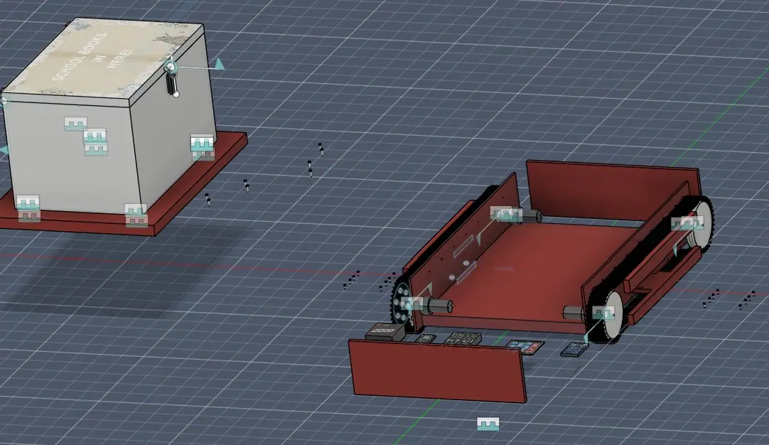
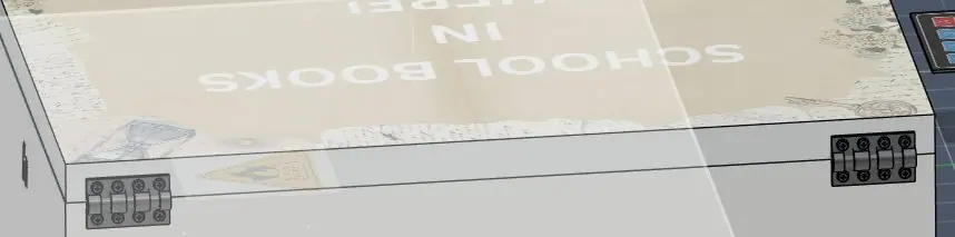
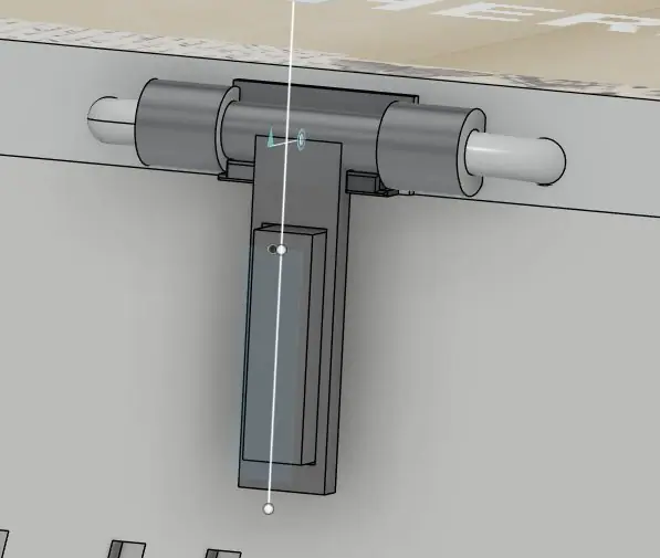
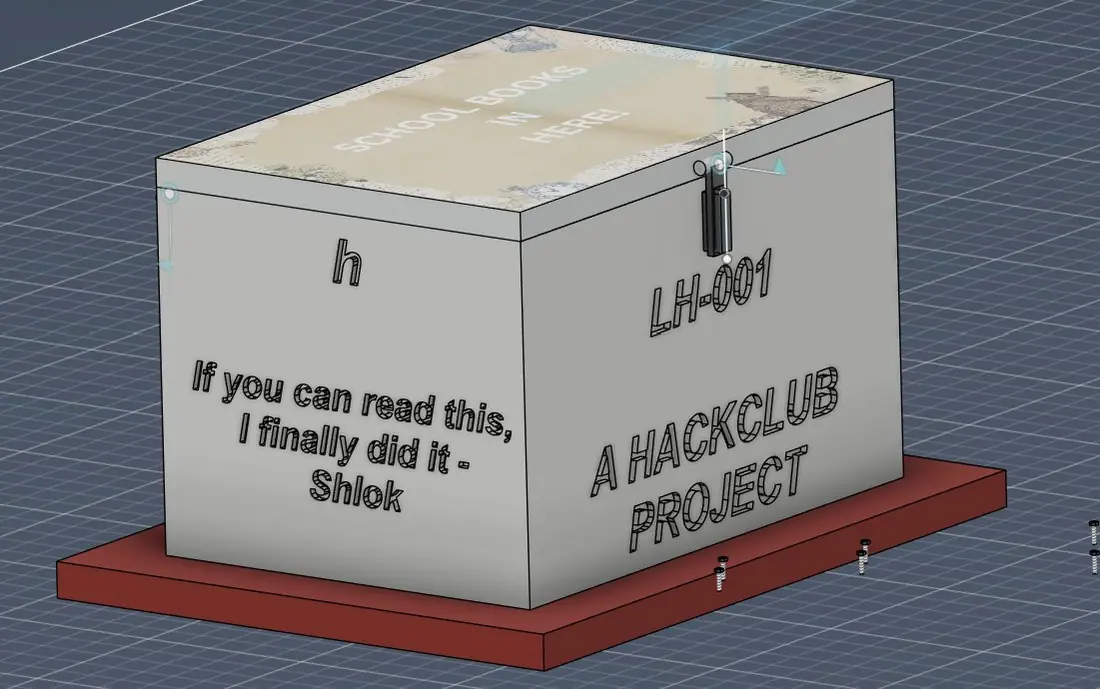
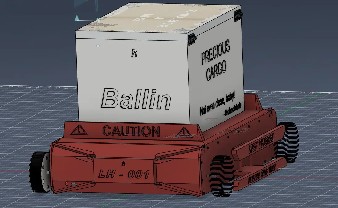
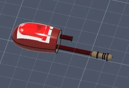
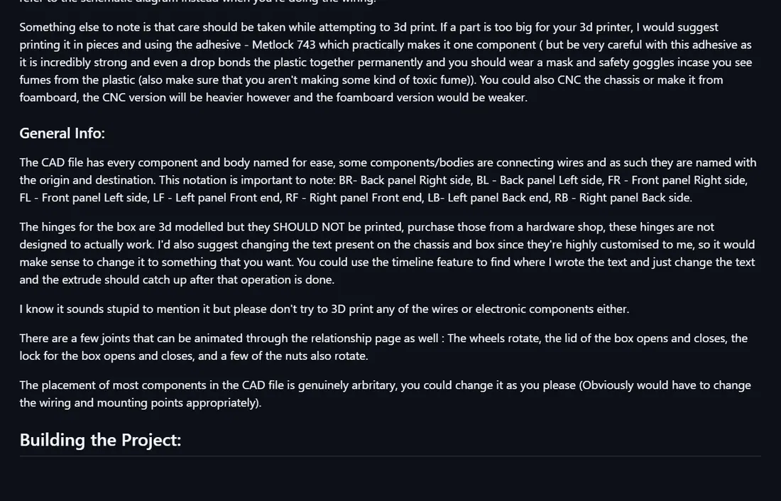
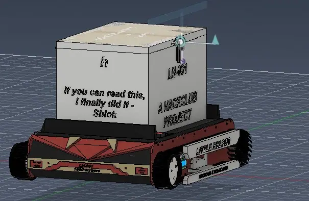
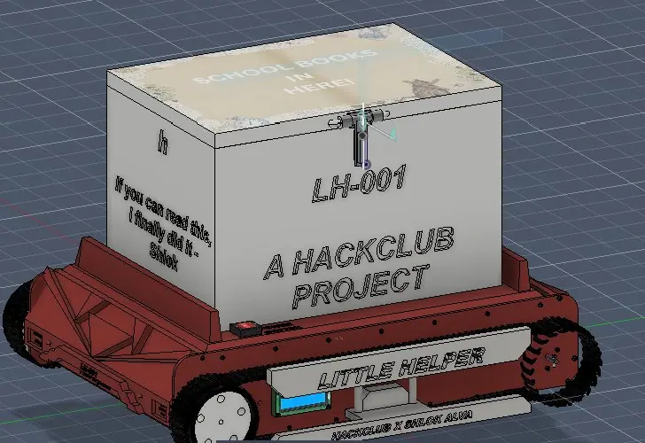
So to start out with my build, I first decided to 3d model the box in which the teachers can place the books and then 3d animate it. I couldn't manage to design exact hinges but I made something that was understandably a hinge. I made a latching mechanism since if the bot is climbing stairs the books falling out would obviously be :(. I made the size of the box A3 with enough height for all the textbooks and notebooks they may carry between classes as well. (The box could be 3d printed except for the hinges as long as you either print it in pieces and use plastic adhesives or just bought from a store like an icebox or made from foamboard with the hinges bolted in (use thick foamboard else the box may tear from the bolts/ the weight). The mechanism to attach the box to the bot will be constructed after I make the bot. I'm not the best at 3d cad design so this was the best I could do. I didn't want an open box because then teachers can have privacy if theyre transporting papers and nothing can fall out as well. The A3 size was chosen since I thought that's the biggest size I've personally seen a teacher carry around my school. The hinges were particulary hard for me to cad design since I'm not good with designing parts that actually fit together, I'm more of a build it in person with cad as a visualisation tool person. The animations helped make sure it all fits together right and moves in the right way and the dimensions and spacing are right. TLDR: made box for the books :D
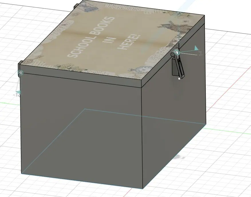
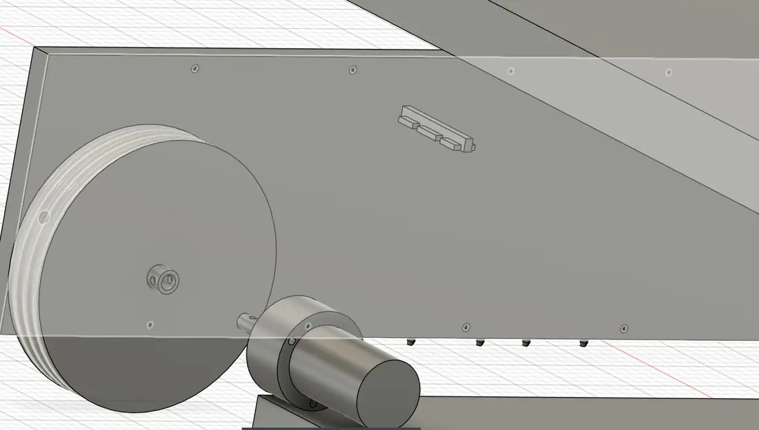
Image 1 from devlog #1: Box
#2CAD FrameworkJun 1, 2026 · 1h 16m tracked · 2 recordings
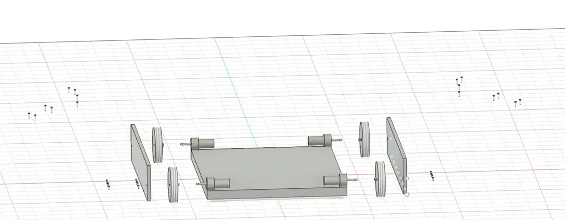
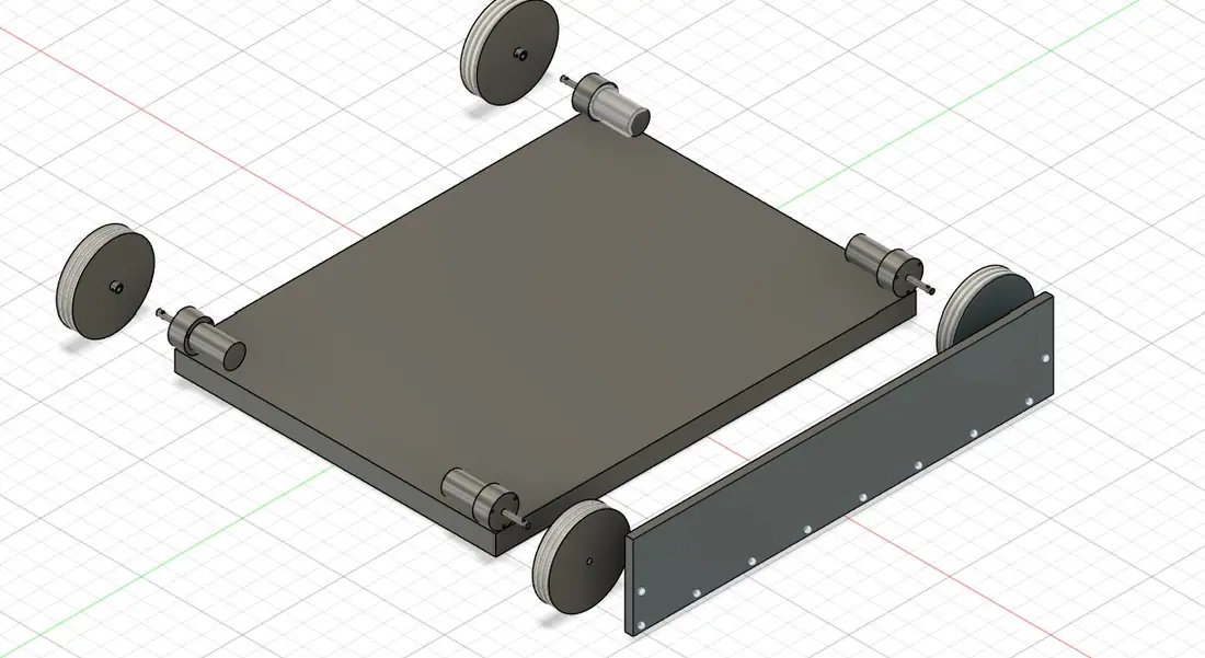
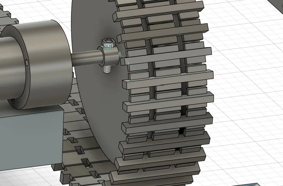
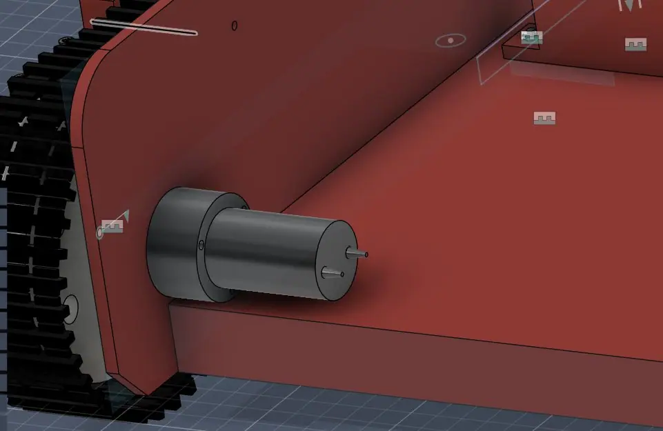
What I did today was I started with the CAD work for the actual chassis, wheels and tracks for little helper. I made a base plate, replicas of the Johnson Grade A 1000rpm motors I'll be using with their L shaped mounting method and the top plate, track link and wheels. I inserted the self tapping screws that attach the side plates to the base and top as well and the m3 screws that attach the wheels to the motors. The motors and wheels can be purchased along with the nuts and bolts and tracks and the rest can be 3d printed, people can even cnc the chassis if they want to avoid it warping from the torque. People can even use different motors if they want but they'd have to change the design. I had to cad one of the hex nuts myself as well since I couldn't find it. I'll do assembly of all of it together once all the parts are ready. I spent a long time deciding how to climb stairs in this bot and I decided on tracks since its the simplest way and the tracks work by a 4wd system where the friction pulls the tracks and guide rails( I still have to cad the rails) hold the tracks in place. It's a very crude track system but it's the best I can do.
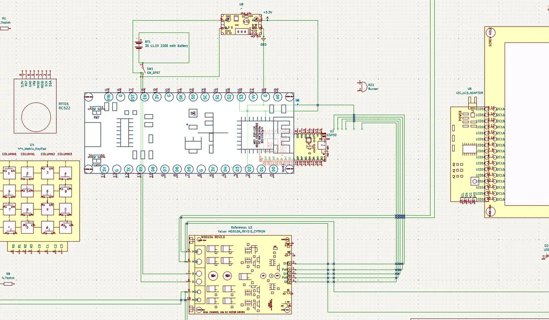
Image 1 from devlog #2: CAD FrameworkImage 2 from devlog #2: CAD FrameworkImage 3 from devlog #2: CAD Framework
#3Basic Tracks and ElectricalsCADJun 1, 2026 · 1 recording

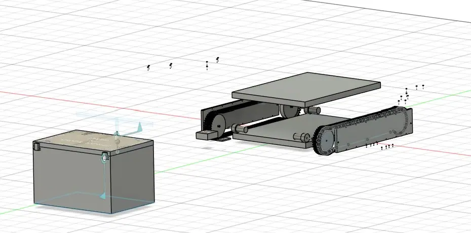
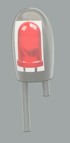
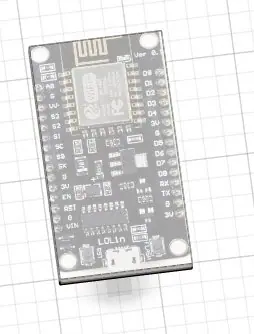
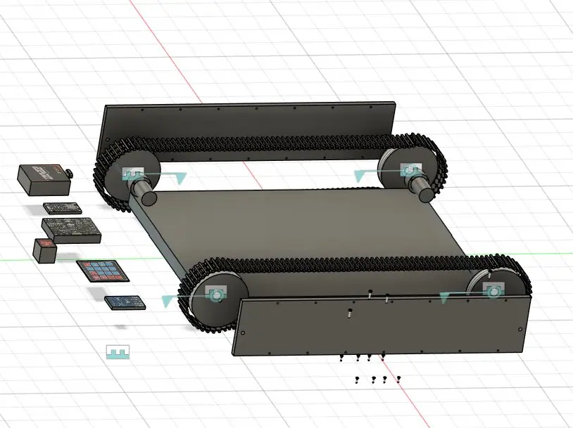
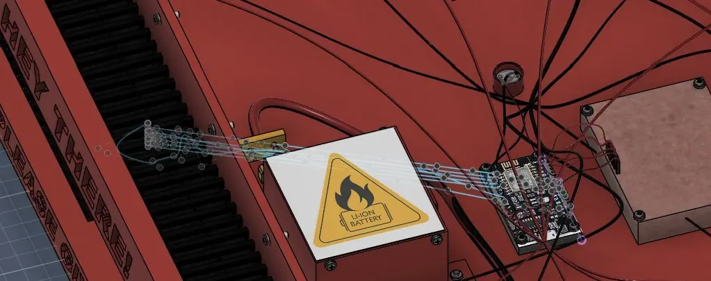
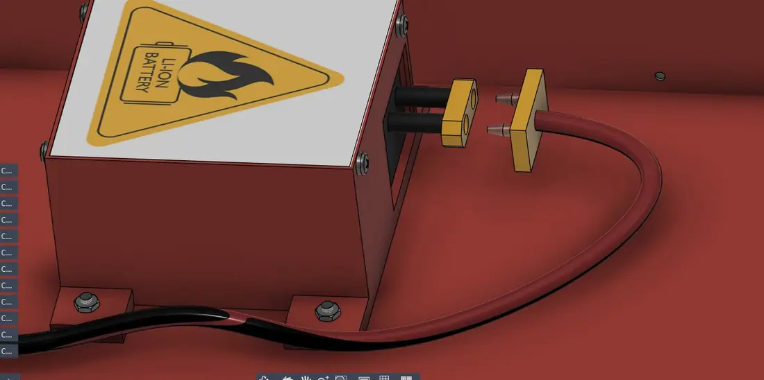
What I did now was I made a 3d version of the battery that I'm using (11.1V 3s Liion 2200mah battery) and of my esp8266 and small electronics components (red led light for warning and buzzer) and I finally made the tank tracks by first making a small piece thats going to be the section and then tracing out a path and making a pattern and it actually ended up looking pretty sick. Doing the design of the tracks helped me realise i miscalculated pretty big and I need 4 of the track sections im ordering and not 2 so that would have been a very big oopsy. The next steps are obviously adding more parts and assembly but atleast its starting to come together and look like a track based robot.

Image 1 from devlog #3: Basic Tracks and ElectricalsImage 2 from devlog #3: Basic Tracks and ElectricalsImage 3 from devlog #3: Basic Tracks and ElectricalsImage 4 from devlog #3: Basic Tracks and Electricals
#4Small Electronics and Moving TracksCADJun 2, 2026 · 1 recording

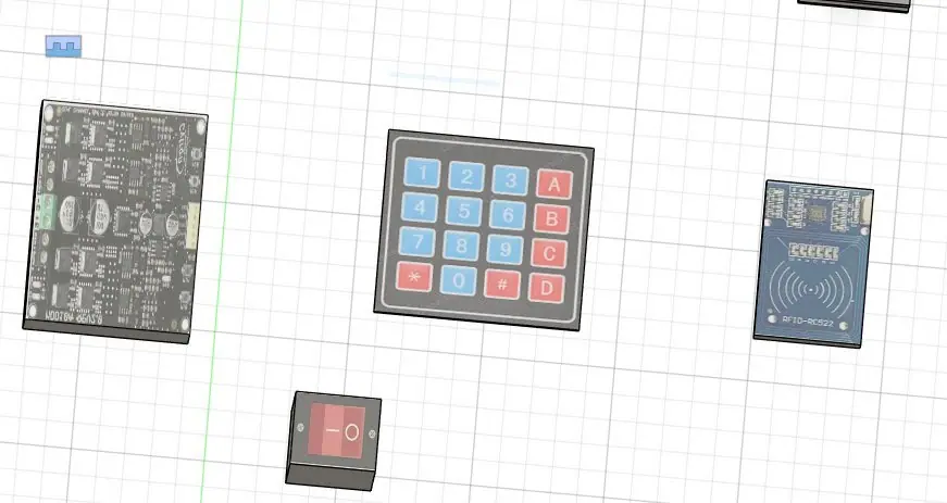
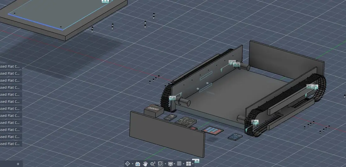
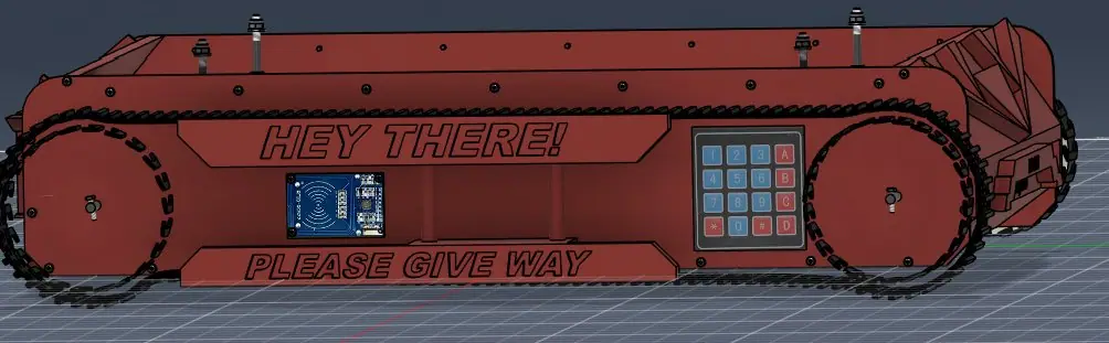
What I did today was I added smaller electronics like the RFID, numkey, motor driver, power switch and then I animated the joints between the motor and wheel and brought the tracks into place. I tried animating the tracks to link to the wheel but I was wildly unsuscessful there. I brought the bolts into place as well for the motor. I decided to just ditch animating the tracks for now (in the CAD model you will see a gap between the tracks and the wheel just ignore this and make sure to tension the track as much as possible without risking it snapping.) I was trying to bring the side plate to the main body when I realised two things, I completely forgot to add the guides and the side plate is way too short. But that is a problem I'll fix in the next journal. As always this project seems way out of my league but we shall keep trying.

Image 1 from devlog #4: Small Electronics and Moving TracksImage 2 from devlog #4: Small Electronics and Moving TracksImage 3 from devlog #4: Small Electronics and Moving Tracks
#5Joints n ChassisCADJun 3, 2026 · 1h 9m tracked · 2 recordings

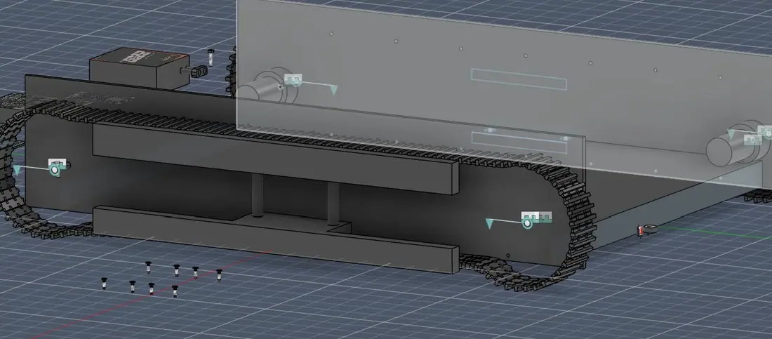
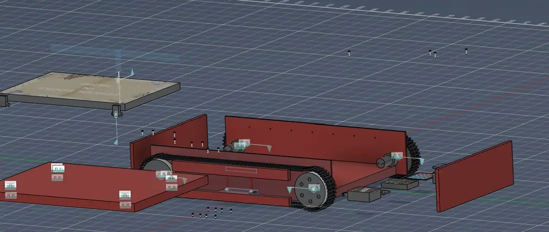
Today I did some pretty basic and unremarkable work. I mostly worked on creating joints between components and fixing the sizing issue that was present for the side plates. I realised that the side plates were too thick to not hit the tracks so I reduced the thickness. I also made the guide rails for the tracks so that they don't fall off since they're purely friction based tracks with no binding mechanism. I added supports for the guide rails and made them a part of the side plate itsself to avoid complicating it. I started with the front and back plates and joining the box for the books to the top plate as well. I didn't achieve nearly as many hours as I wanted to today and I have to absolutely lock in if I want to make it to fallout.

Image 1 from devlog #5: Joints n ChassisImage 2 from devlog #5: Joints n Chassis
#6General ImprovementsCADJun 4, 2026 · 1h 2m tracked · 1 recording

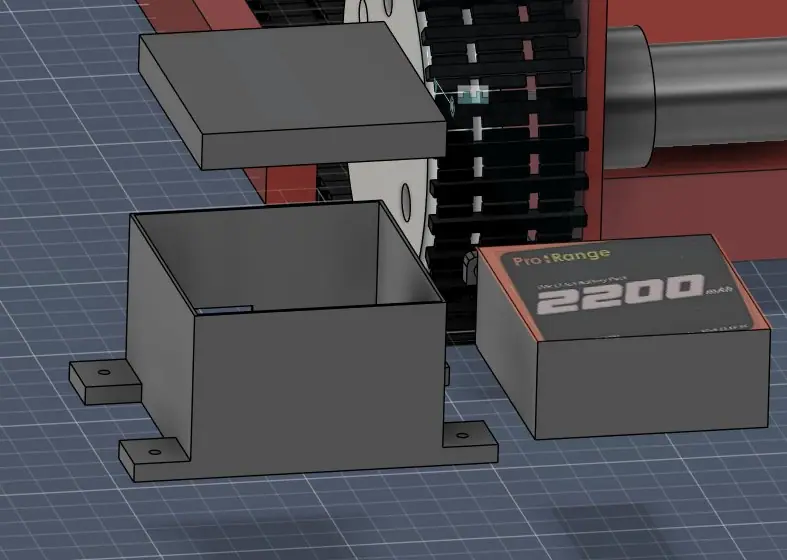
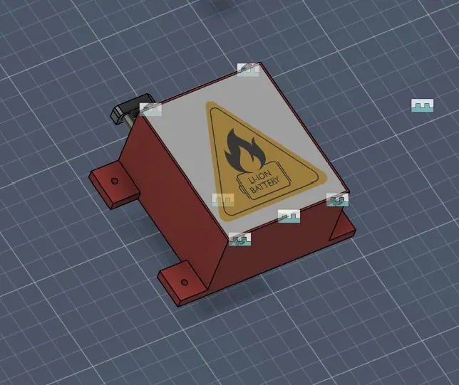
So today to start off the day, I first added the bolts and nuts to hold the box to the top plate and then I started changing the appearance and material of all the components to make it more accurate and for aesthetics. I also started making a battery holder and added little terminals to the motors. I made the wheels resemble what they look like in real life as well. And that's about it really.

Image 1 from devlog #6: General ImprovementsImage 2 from devlog #6: General ImprovementsImage 3 from devlog #6: General Improvements
#7Tracks, Aesthetics, Tires and JointsJun 4, 2026 · 1h 45m tracked · 2 recordings

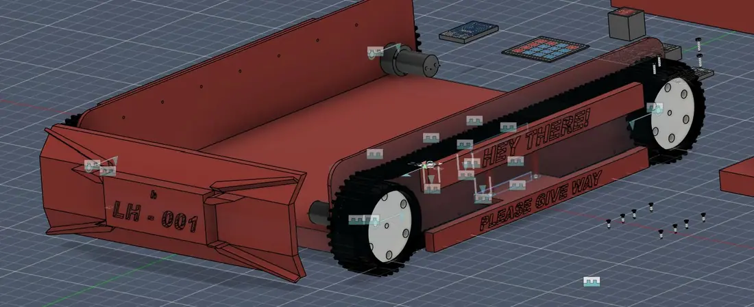
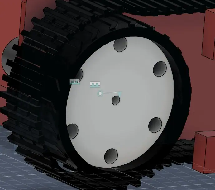
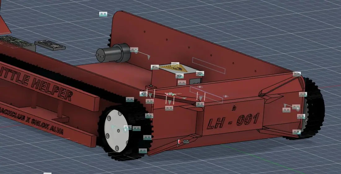
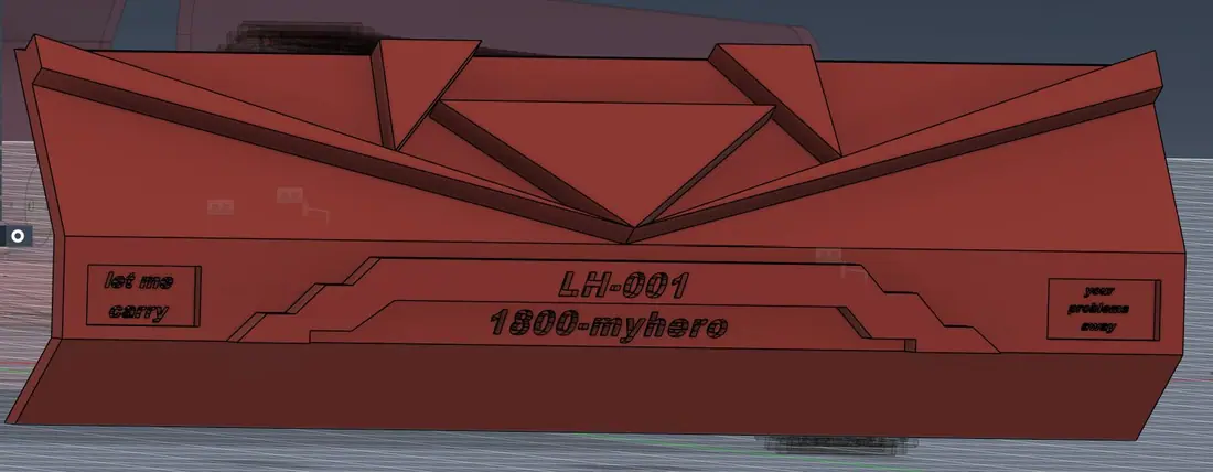
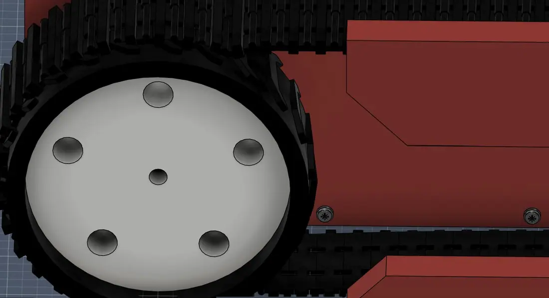
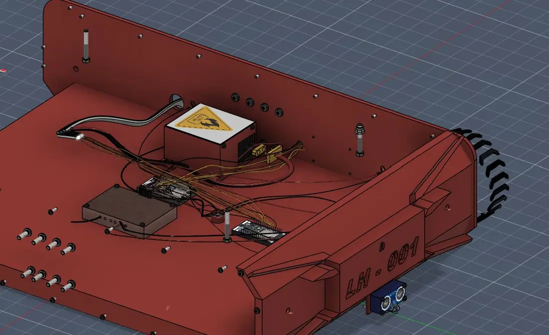
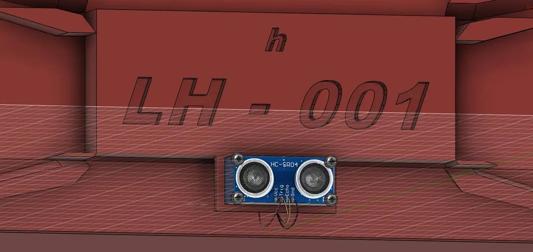
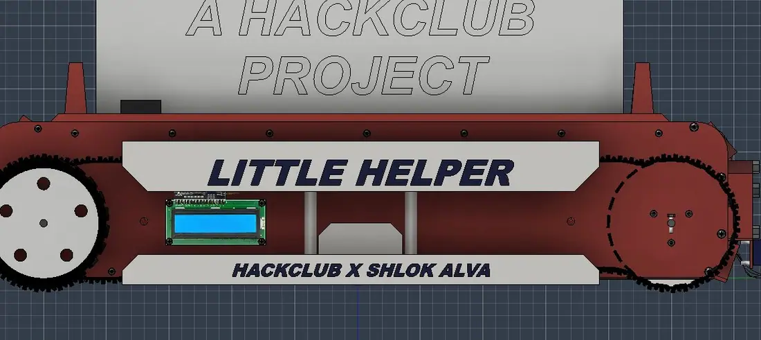
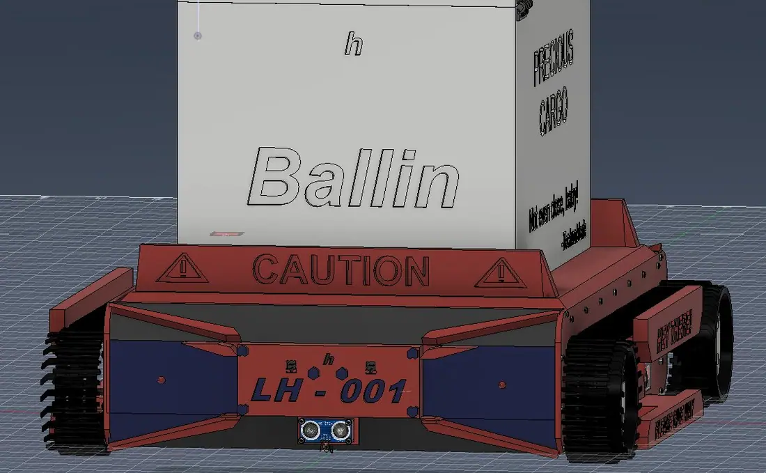
What I've done now has actually been really productive, I worked on the battery holder and fixed some joints and decals and designed the battery holder with all the mounting screws decals and a hole for the wiring as well. The more exciting part though is what I did after, today I finally got rid of that ugly looking threading on the tires and replaced it with actual tire tread and that honestly looked amazing. I also changed the side plates so they actually have a design element to them and are no longer just flat rectangles now. On the guide rails as well I added some text. The most drastic change in terms of apppearance is the front plate which has gone from a flat rectangle to an actual really cool design that I'm pretty proud off, I learnt how to use the emboss tool just for that. I also added materials again especially rubber to the tracks and tires. I put some text on the front as well as a kind off joke number plate. The design actually looks pretty alright, and despite the fact that to most it probably still looks abysmal I'm suprised I managed to get this far. Hopefully the rest of my days stay this productive. Shenzen here I come. For tomorrow I'm going to work on the back plate and some more aesthetics as well as moving the electronic components in, trying to see if I can actually make links for the tracks and who knows what else.

Image 1 from devlog #7: Tracks, Aesthetics, Tires and JointsImage 2 from devlog #7: Tracks, Aesthetics, Tires and JointsImage 3 from devlog #7: Tracks, Aesthetics, Tires and JointsImage 4 from devlog #7: Tracks, Aesthetics, Tires and Joints
#8BackplateCADJun 4, 2026 · 57min tracked · 1 recording

To sign off for the day I made the backplate design, similar to the front and with its own text as well. I then moved and attached the front plate to the side plates with screws and I also learnt how to use the activate component tool and how to switch back to be able to work on the project easier. It was a long tiring and productive day, and hopefully tomorrow will be more of the same.

Image 1 from devlog #8: BackplateImage 2 from devlog #8: BackplateImage 3 from devlog #8: BackplateImage 4 from devlog #8: Backplate
#9Guidelines & BoxJun 5, 2026 · 2h 6m tracked · 1 recording

To start today first I updated the guide rails to make them look better by adding some detailing. I joined the back plate to the main chassis as well with bolts and all which was difficult because of all the overlap. I resized the bottom plate a bit to accomodate the back plate as well. All of the fasteners I've used so far have been placed in holes with modelled threading as well. Then I attached both side plates to the bottom plate of the chassis with screws as well. I also remodelled the hinges of the box completely since they looked horrible before. I added some text to the sides of the box as well for some design elements.

Image 1 from devlog #9: Guidelines & BoxImage 2 from devlog #9: Guidelines & BoxImage 3 from devlog #9: Guidelines & BoxImage 4 from devlog #9: Guidelines & Box
#10Aesthetics, Electronics and A Buggy FusionCADJun 5, 2026 · 1h 55m tracked · 1 recording

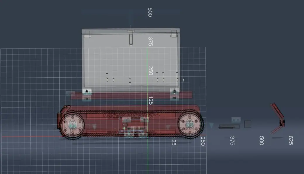
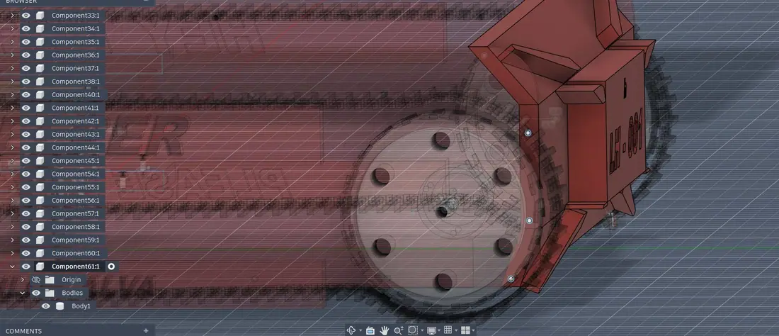
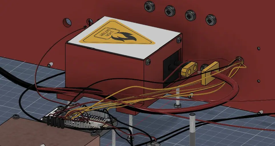
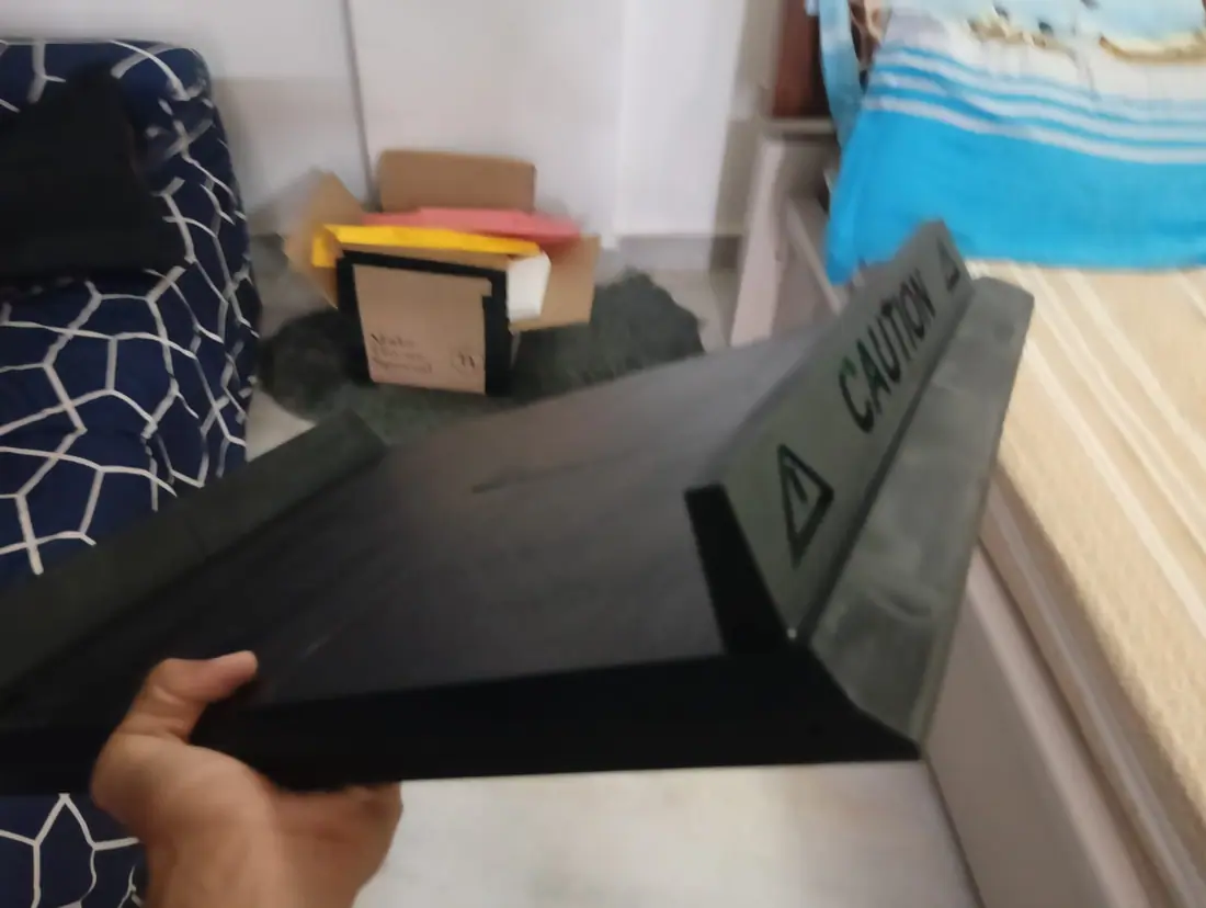
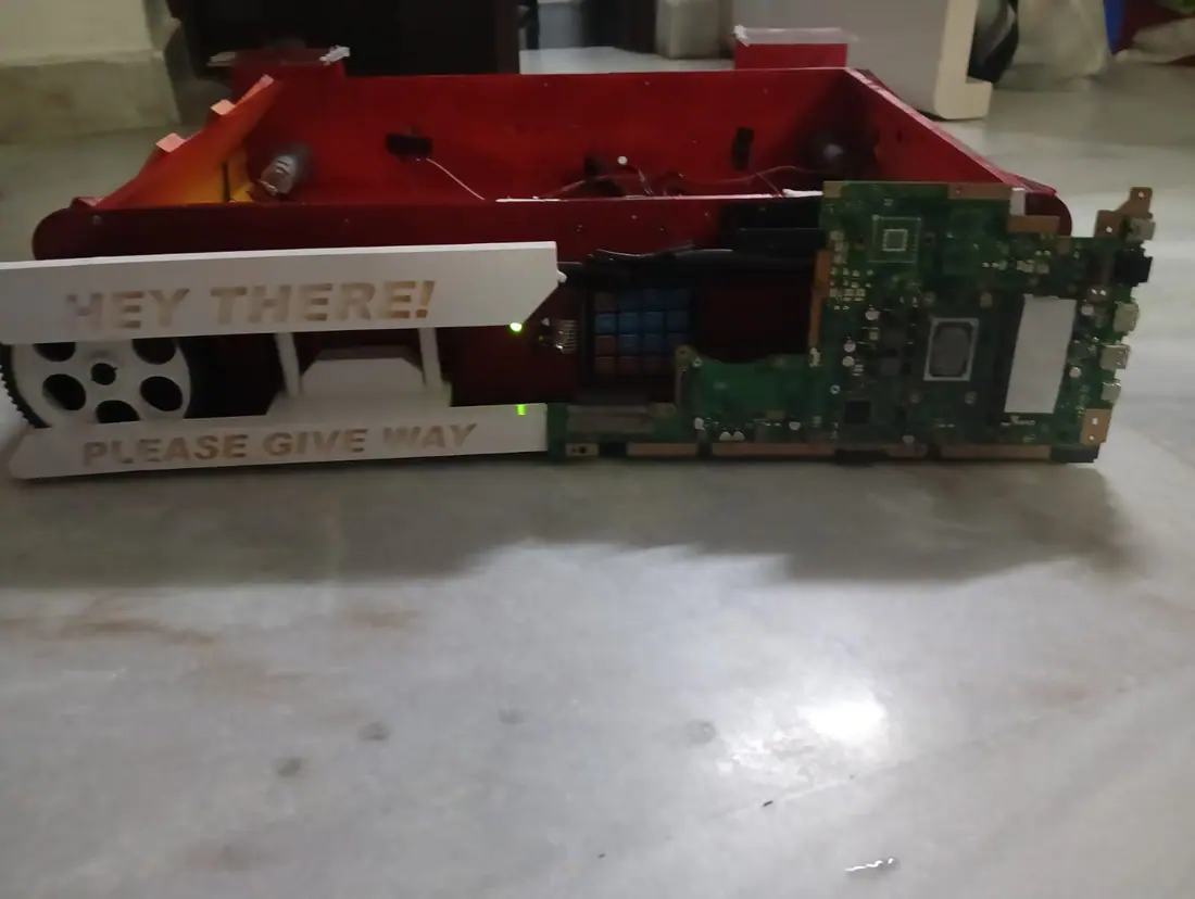
What I've done now is I've made the top cover look better and then moved the entire top with the box to the main chassis which was incredibly frustrating since it didn't want to move together no matter what I tried, and it put my screws in the middle of nowhere miles apart (shown in photo) and moved parts into the middle of the box for some reason as well which was ridiculously frustrating so I just remade the parts. The infinite amount of parallax error also drove me absolutely nuts. After that, once the top plate was adjusted properly and bolted in I started moving the electronic components in, and screwing them in until I realised that in my infinite wisdom I didn't leave any space for the RFID and numkey. So I had to chop the guiderails on one side to fix this, which is a bit odd but is my best option all things considered. After fixing this and a few other misconfigured joints, I also had to redo the canvases since they were seen across the project, weren't selectable and didn't move with the objects. I also added a caution plate on the front. Fusions view movement tool also keeps bugging out and I think I might lose my mind.

Image 1 from devlog #10: Aesthetics, Electronics and A Buggy FusionImage 2 from devlog #10: Aesthetics, Electronics and A Buggy FusionImage 3 from devlog #10: Aesthetics, Electronics and A Buggy FusionImage 4 from devlog #10: Aesthetics, Electronics and A Buggy Fusion
#11Wiring Motors and ElectronicsCADJun 6, 2026 · 1h 50m tracked · 1 recording

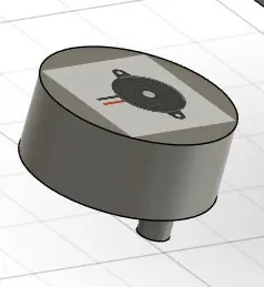
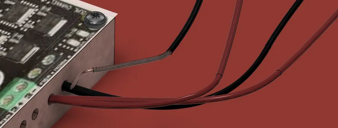
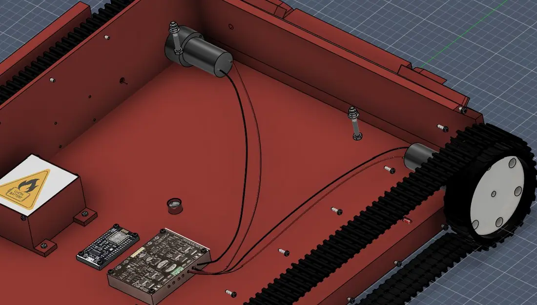
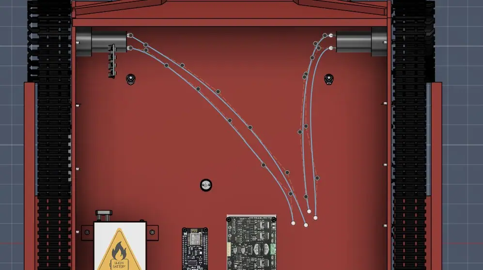
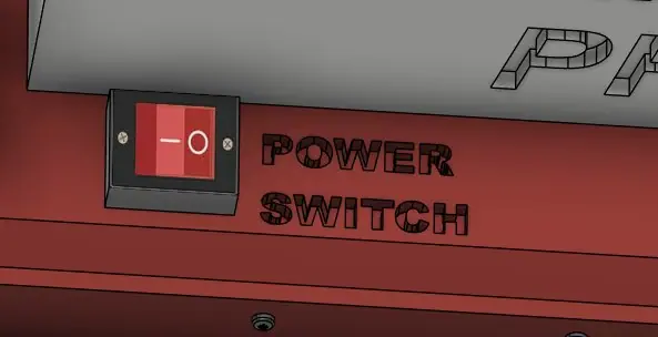
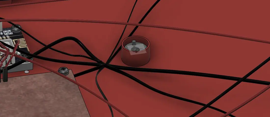
To start off the day, I first increased the height of the guide rails since I realised that they weren't really guiding anything, and checked that the bottom rail wasn't touching the ground. Then I redesigned the leds a bit and put them in set placed holes around the chassis. Then I fixed the RFID positioning and some faulty joints for that. I've finally reached the unfortunate point where fusion lags especially if I try to change old components so that's a bit annoying, and hopefully I finish the CAD work soon. I had to stop recording for a while as well since I was just waiting between clicks to delete the rfid linkages cause I had to redo that completely. I also added a little holder for the buzzer to sit in (didn't seem necessary to make a locking mechanism for it so it just sits in place). Added a power button to the top as well. I fixed some mismatched spacing on the bottom plate as well. I then started making the connecting wires between the motors and the motor driver. The level of detail I'm trying to add is making my computer genuinely tweak. I tried to join each connecting wire to the motor driver with smaller copper wires but after getting a horrible result and incredible lag with one soul sucking wire I decided only to keep 1 connected properly and the rest differently. Next up would be finishing the wiring for the rest of the parts and some final polish work cause I'm genuinely done with this CAD work.

Image 1 from devlog #11: Wiring Motors and ElectronicsImage 2 from devlog #11: Wiring Motors and ElectronicsImage 3 from devlog #11: Wiring Motors and ElectronicsImage 4 from devlog #11: Wiring Motors and Electronics
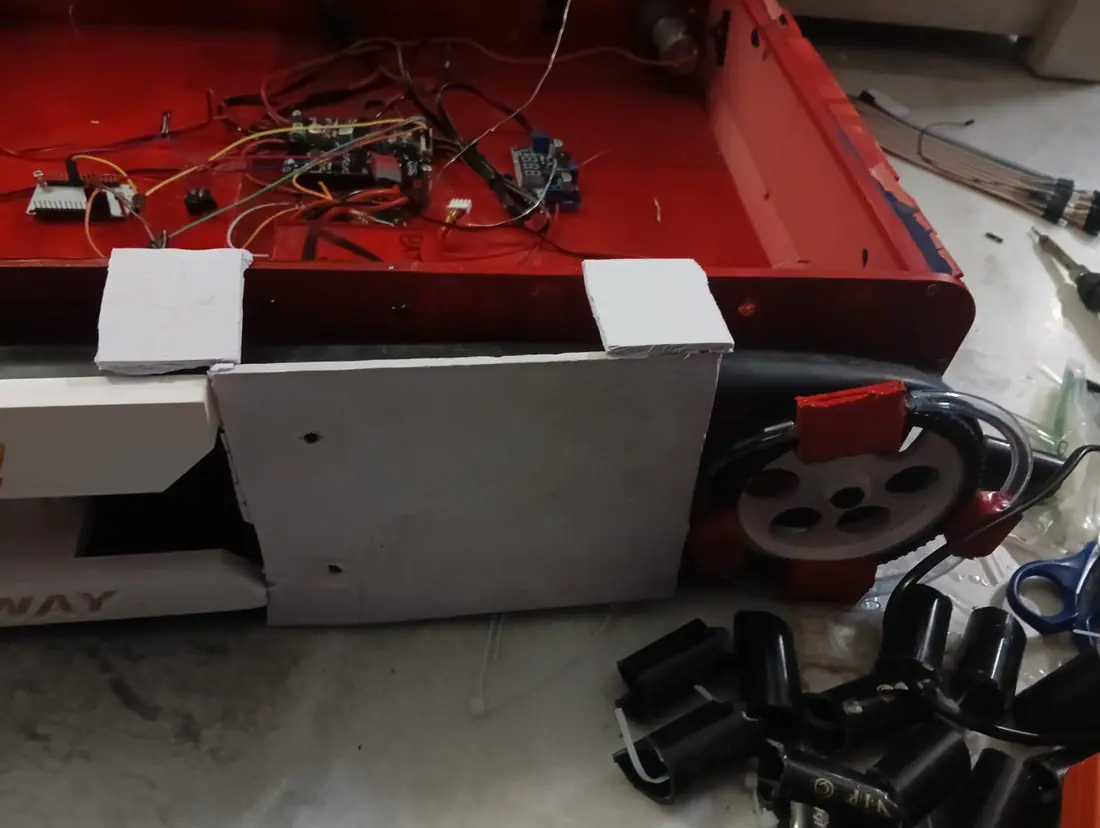
#12Resistors, Guidelines and WiringCADJun 6, 2026 · 3h 2m tracked · 1 recording

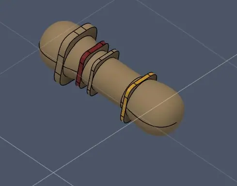
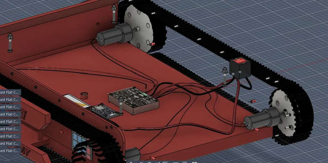
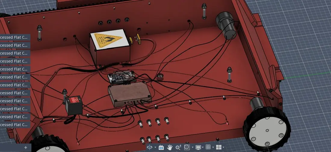
I started off by finishing the motor wiring into the motor driver, then I worked on getting the power switch, battery and motor driver connected. In my attempt to make a good battery wire, I completely crashed my fusion ( thank god for recovery files ). I've never made any splines in 3d so I had no clue how but a few crashes and recovery files and a whole lot of frustration and tweaking later I finally made a whole one wire for the battery connector. This would have been a very usefull tool to have known for the motor driver wires but alas. I connected the battery wire to position of the battery and then made a connector head for it and detailed that. Was all that detailing time worth it? I damn well hope so. I also fixed another missing screw. I connected the button to the motor driver as well which was a lot easier since I had already learnt the trick.
I then made a little resistor for the led lights since thats a very important component not to forget in the build. Then I added a way to attach the sideplates with the guidelines to the main chassis instead of printing it as one part since it's pretty big. I also fixed some placement issues since for some reason my files placements got messed up. I also made some holes for wires for the rfid and numkey ( The rfid will be used for teachers to scan their access card and the numkey to enter the classroom.).

Image 1 from devlog #12: Resistors, Guidelines and WiringImage 2 from devlog #12: Resistors, Guidelines and WiringImage 3 from devlog #12: Resistors, Guidelines and WiringImage 4 from devlog #12: Resistors, Guidelines and Wiring
#13LEDs, Wiring and TracksCADJun 7, 2026 · 1h 52m tracked · 1 recording

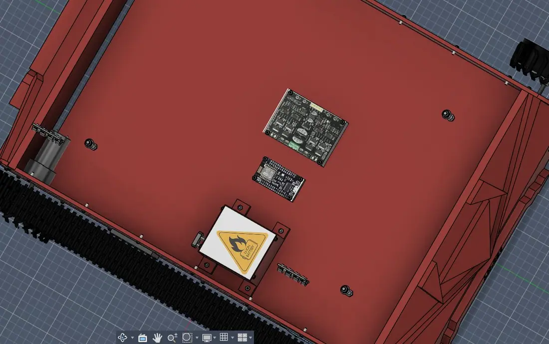
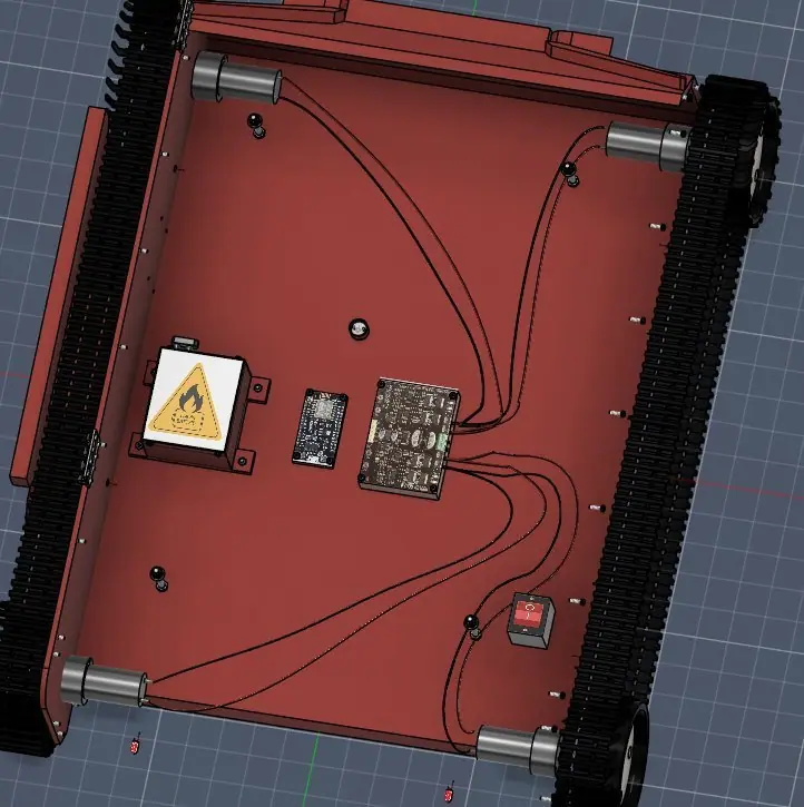
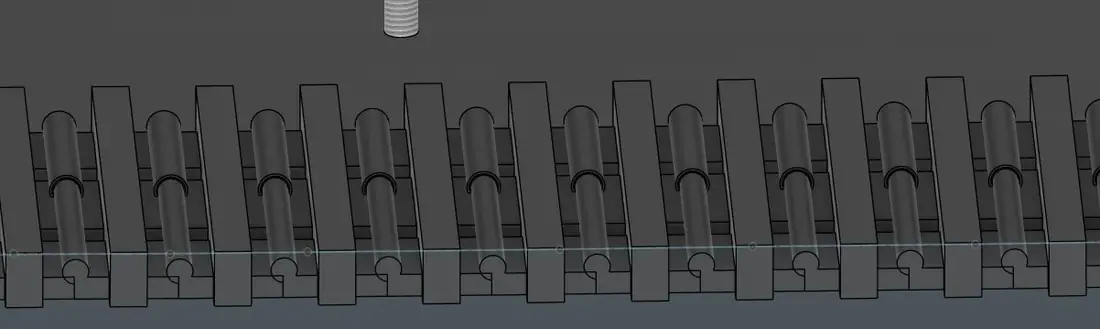
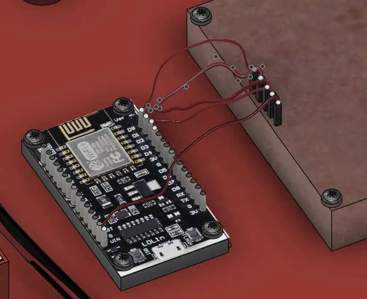
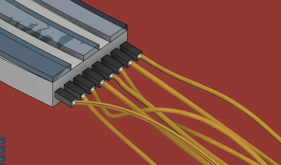
To start out today I moved the resistors to the LED lights. I then made some pin headers for the ESP8266 and the motor driver and made the connections between them as well. Then I tried to move the tracks so they actually sat on the tires instead of magically levitating. I first tried to do this by changing the spline sketch over the wheels until after doing that I realised that it was the position of the first link that affected that so I in essence wasted all my time. Fusion also keeps randomly closing when it lags, which is becoming very ominous. I also changed how the tracks look by adding the actual links between the individual chain pieces to make the tracks slightly better. I had to readd some resistors since for some reason half of them just vanished and kept dissapearing. I connected all the leds to the esp as well after checking that it wouldn't fry the esp. Next up I have to wire the ground for the leds, make an ultrasound sensor and place that and then I have to wire the rfid, numkey, and the ultrasound and code it all as well which is a part I'm not particularly looking forward to rn. What's really cool though is you can see my CAD skills improving through this project.

Image 1 from devlog #13: LEDs, Wiring and TracksImage 2 from devlog #13: LEDs, Wiring and TracksImage 3 from devlog #13: LEDs, Wiring and TracksImage 4 from devlog #13: LEDs, Wiring and Tracks
#14Ultrasonic sensor and LED wiringJun 7, 2026 · 1h 23m tracked · 1 recording

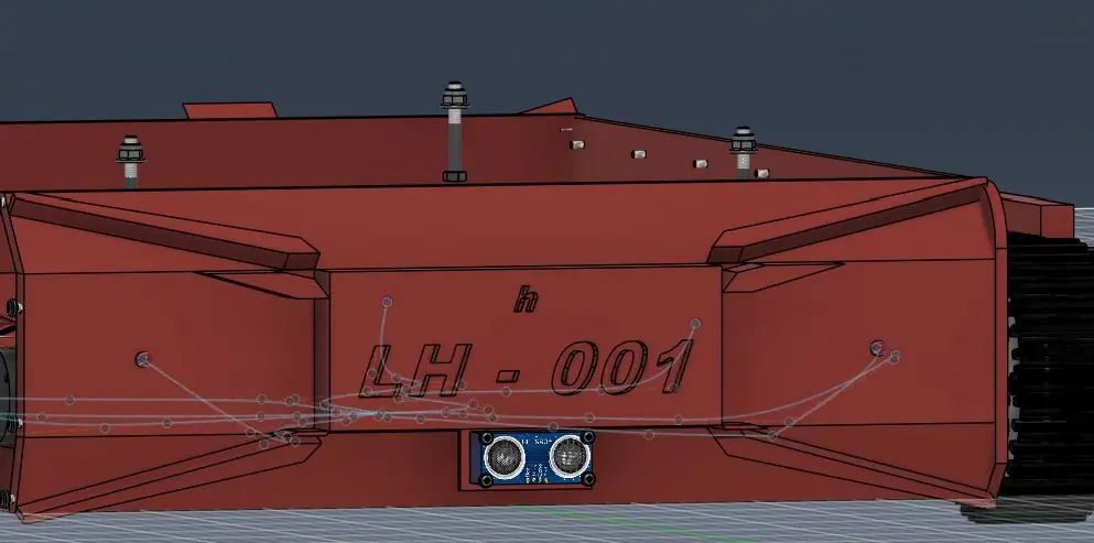
To sign off for the night, I first made the ultrasound sensor and a plate for it and attached it to the front, which doesn't look the best but since it's necessary there isn't really a choice. Then I made the wiring for the -ve wires for the LEDS which I had to do twice since it didn't work the first time around. I also realised the reason everything kept getting messed up is I accidentally keep moving components like the base plate :D. And that's it for tonight.

Image 1 from devlog #14: Ultrasonic sensor and LED wiringImage 2 from devlog #14: Ultrasonic sensor and LED wiringImage 3 from devlog #14: Ultrasonic sensor and LED wiringImage 4 from devlog #14: Ultrasonic sensor and LED wiring
#15RFID and Buzzer WiringJun 8, 2026 · 26min tracked · 1 recording

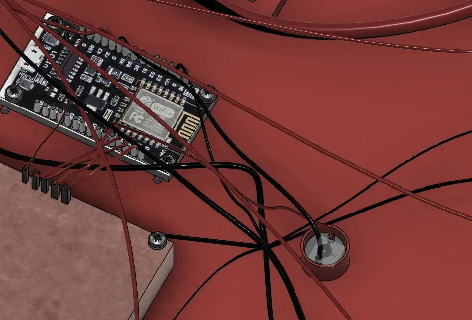
I was a bit busy today so my logged hours ended up coming up under my goal. I started out with connecting the buzzer to the ESP's ground and GPIO pin. Fusion and my laptop are really struggling now with the number of components so after the wiring for the rest of the components and the aesthetic design updates I'll stop my CAD work. Next I did the wiring for the RFID (Didn't finish it though). In the middle of all of this lookout started tweaking out as well which was not helping at all. Not a very productive day but what can you do.

Image 1 from devlog #15: RFID and Buzzer WiringImage 2 from devlog #15: RFID and Buzzer Wiring
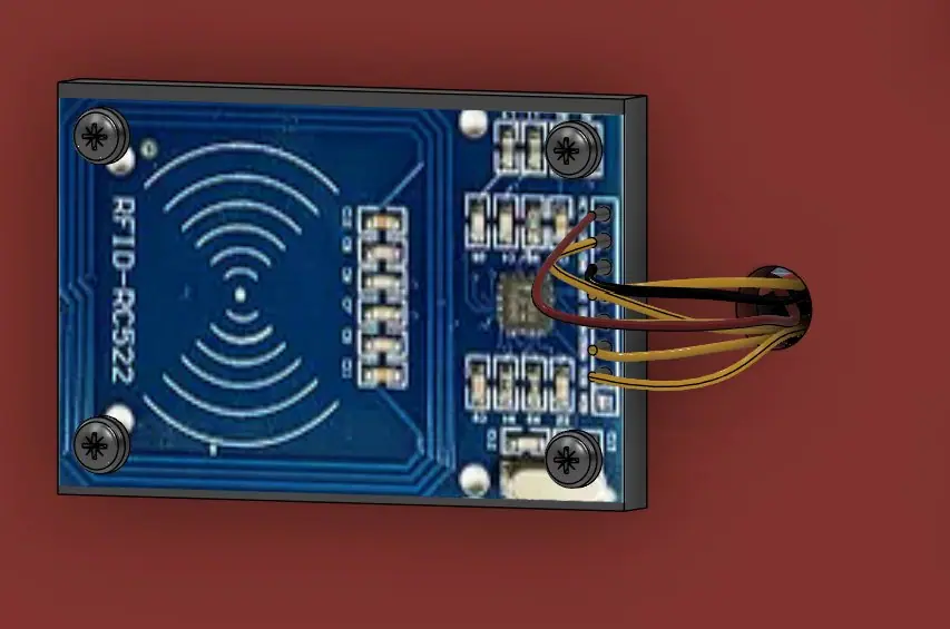
#16RFID WiringCADJun 9, 2026 · 1h 8m tracked · 1 recording

Today, I resumed with the rfid wiring but realising that I couldn't make the RFID sketch for the wires work I decided to redo the sketch one by one. The lag is honestly becoming incredibly frustrating. Every single new action is starting to lag out fusion and I can't pause lookout everytime since its 10s of lag and I loose a minute of recording but I realised I could just hide most components and that may help a little. Something else that I really need to figure out is the automation aspect, as until now I've been thinking of rotary encoders/hard coded paths but that seems like poor implemenation but I'm absolutely unfamiliar with LIDAR, and I don't want a line follower. The wiring in CAD will act as a very basic reference but the wirings from here absolutely shouldn't be followed (I'll make a schem diagram that should be used instead). I also realised I should 100% rename all components and bodies since I spend forever just looking for it in the browser and anyone trying to recreate it will face the same issues. I also realised while connecting the RFID that I don't have enough pins, so I decided that I'll connect a slave arduino uno as well.

Image 1 from devlog #16: RFID WiringImage 2 from devlog #16: RFID Wiring
#17Numpad Wiring and LCDCADJun 9, 2026 · 1h 43m tracked · 1 recording

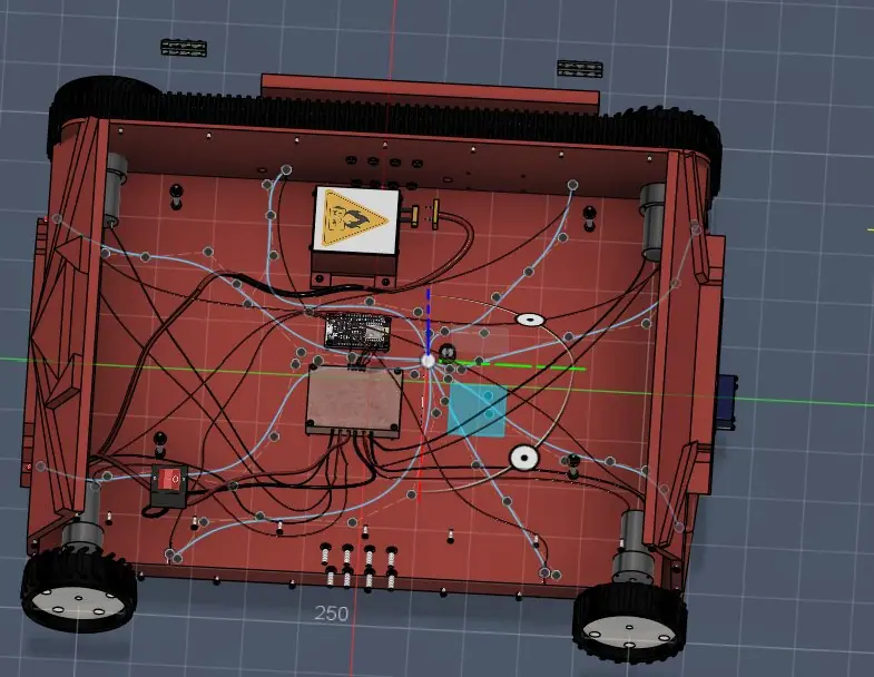
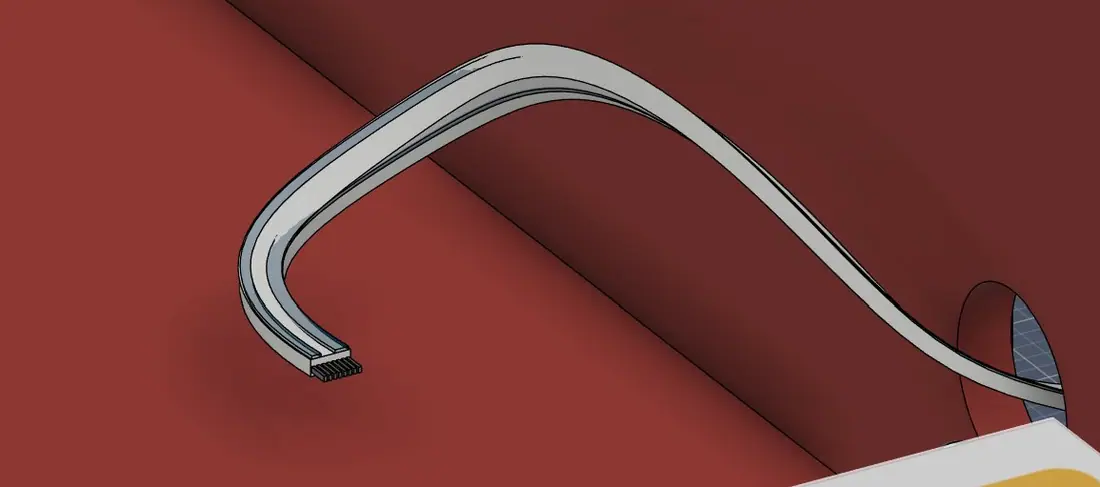
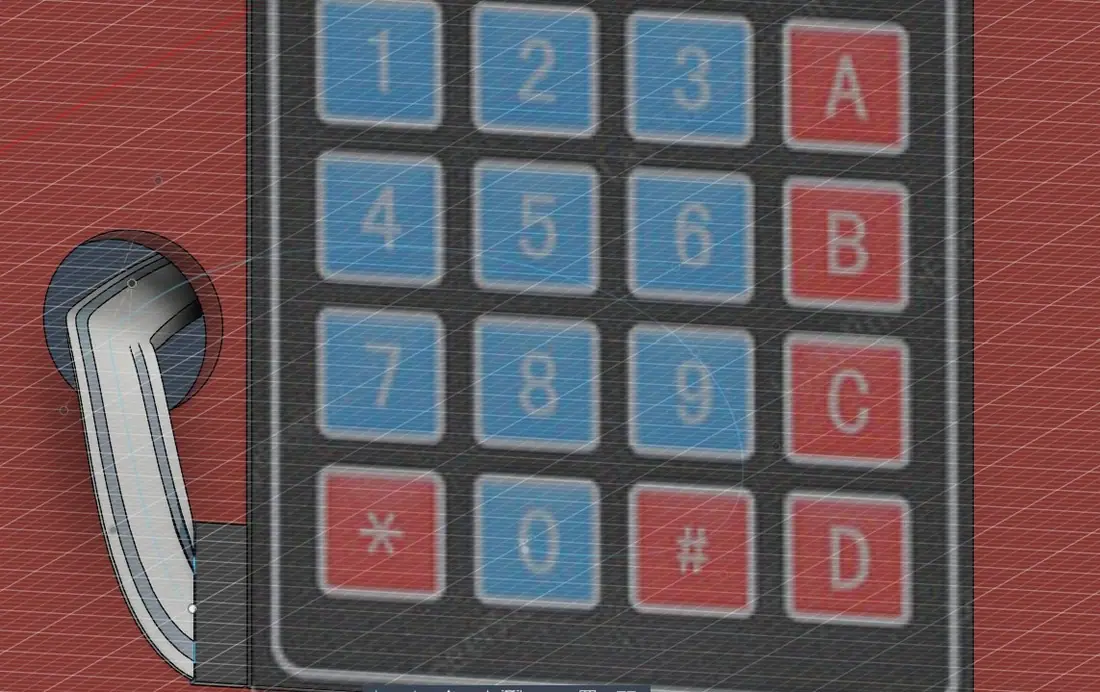
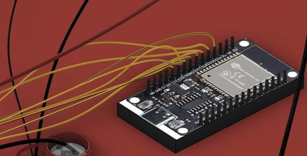
I started making an arduino Uno model as a slave to the esp 8266. I've used an esp8266 and an arduino since that's what I have, but people could use rasberry pis, arduinos,esp32s or whatever suits them better. I also realised that an led/lcd display is pretty much necessary for any info to be displayed. I also made an LCD screen model and wired the numkey to the arduino. I even modelled the cable from the numkey to look like a proper cable and gave all the pin headers to the arduino and connected the arduino to the esps VIN pin. The components keep shifting and causing alignment issues and I have no clue what to do with that at this point so for the time being I just have to ignore it. Everytime I think I'll be done with the CAD soon, I realise I have something or the other to add. I think something I'm also going to do is I'm going to make the bot manually controlled initially, and if feasable add capabilities for autonomous navigation. The wiring to me is by far the hardest part of the CAD work.
Unfortunately my fusion shut and since I hadn't saved literally all the work I did in this log just vanished infront of my eyes. Definitely the hardest day to power through yet. Redoing all of the work is just heartbreaking.

Image 1 from devlog #17: Numpad Wiring and LCDImage 2 from devlog #17: Numpad Wiring and LCDImage 3 from devlog #17: Numpad Wiring and LCD
#18Even More WiringCADJun 10, 2026 · 1h 39m tracked · 1 recording

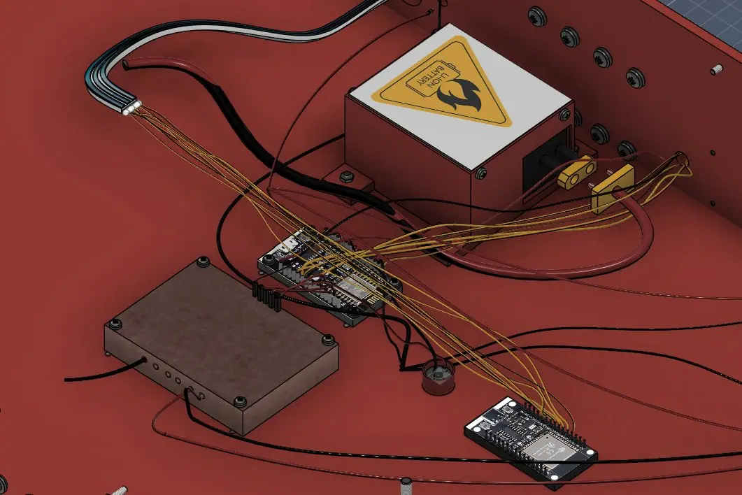
To start off for today, I first had to surmount the tragic task of redoing all the work that was lost yesterday in the fusion crash. I realised my C drive was completely filled so hopefully giving that more space and constantly saving my files is going to save me now. I had hoped that having done it before it would turn out better than previously and in faster time, but this run had its own complications.I really can't wait to start building, I feel like skipping the coding and diagram schematics so bad. I also decided to ditch the Arduino Uno and keep a ESP32 as my device with an 8266 as secondary. I realised I completely forgot to put spacers for any of the electronic components, so that's something I'll have to include in the readme. For some reason Fusion is failing to make recovery files, so I better keep saving and praying nothing goes wrong. I was thinking of just using the same spline to make lofts for wires but the wires start looking so identical that it loses its charm and it doesn't always work. The messy wires are kind of like perfection in inperfection. I just made the base plate unselectable temporarily so that I don't accidentally move it around even more. I have a few more things to wire, and some aesthetic design after which I think I'm going to make the robot first drivable via a ps5 controller, and later on add autonomous capability, I was going to have it controlled via a phone before but since I have an esp32 now, I can use this instead.

Image 1 from devlog #18: Even More WiringImage 2 from devlog #18: Even More WiringImage 3 from devlog #18: Even More WiringImage 4 from devlog #18: Even More Wiring
#19The Infinite WiringCADJun 10, 2026 · 53min tracked · 1 recording

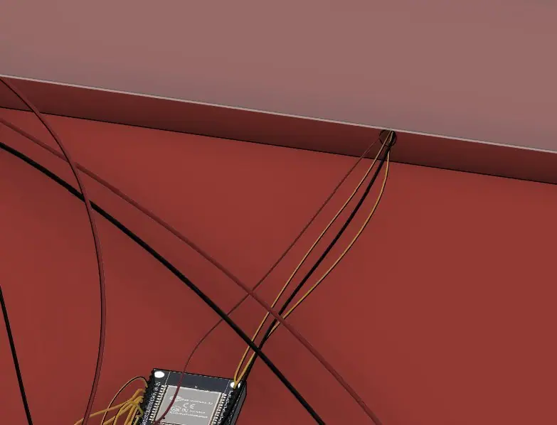
I decided I should definitely rename all the bodies and components right after I finish the wiring, since I spent a solid 5 minutes just looking for the front plate just to know where the hole for the ultrasound wires was which is obviously ridiculously inneficient. I wired the ultrasound sensor, the esps together and screwed down the esp. I decided to model all the lidar stuff after I actually finished the lidar code and decisions and stuff way later down the road. I'm spending every breathing moment that I'm free on this project and its making me feel so tired, and the lack of sleep is really getting to me. I realised 5v power is an issue so I connected both the ESP32 and the ultrasonic sensor to the motor drivers 5v out in parallel to the 8266.

Image 1 from devlog #19: The Infinite WiringImage 2 from devlog #19: The Infinite WiringImage 3 from devlog #19: The Infinite Wiring
#20Renaming ComponentsCADJun 11, 2026 · 1h 12m tracked · 1 recording

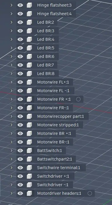
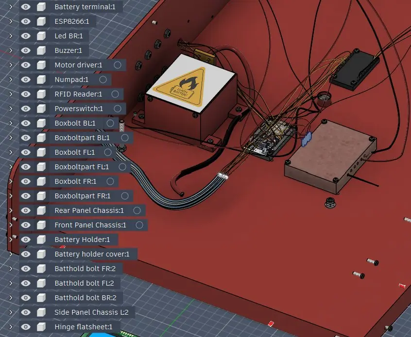
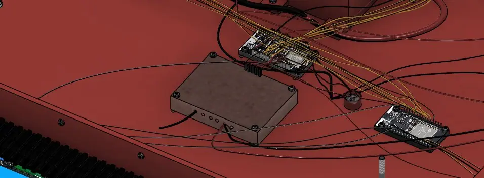
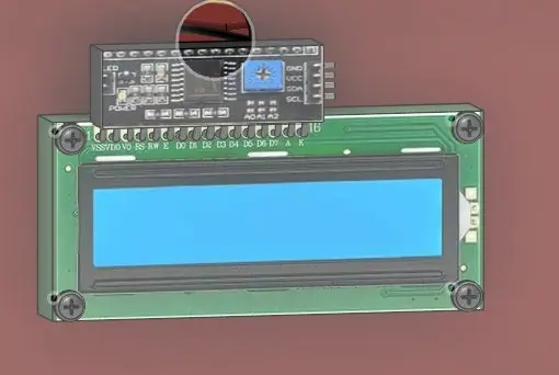
To start off I decided to rename all the components, since Its really hard to show and hide components when I'm manually spending so long just scrolling through components, plus it adds a level of polish to the cad file. Just my luck fusion crashed once again, and I was so happy to see a recovery file but even that was corrupted, I don't know what the hell this luck is, but I redid it nevertheless. I'm looking forward to saving the final file and not touching it until I need to cause I'm fed up of the lag and crashes, I'm going to save so frequently now. I named some of the bodies as start and end when there were just 100 mirrored parts instead of taking ridiculous time to rename each one. Next, I moved the LCD display into place and added an I2C adaptor which I still have to finish modelling but will save me a lot of pins.

Image 1 from devlog #20: Renaming ComponentsImage 2 from devlog #20: Renaming ComponentsImage 3 from devlog #20: Renaming ComponentsImage 4 from devlog #20: Renaming Components
#21LCD and I2C AdaptorCADJun 11, 2026 · 1h 5m tracked · 1 recording

I finished the modelling for the LCD screen and its I2C adapter and then wired it to the ESP32. I spent 5 minutes just trying to figure out why my splines weren't working right just to realise I hadn't enabled my sketches to be 3d. The only downside of using the esps is I have such a huge lack of 5v pins so I have just everything running in parallel so hopefully the current draw isn't too much. I also realised that My original plan of having the charger protruding out the back to just be able to plug it in would no longer work considering I have nowhere to put the charger so I just gave up on that idea for now.

Image 1 from devlog #21: LCD and I2C AdaptorImage 2 from devlog #21: LCD and I2C Adaptor
#22GitHub Repo and ReadmeDOCSJun 12, 2026 · 48min tracked · 1 recording

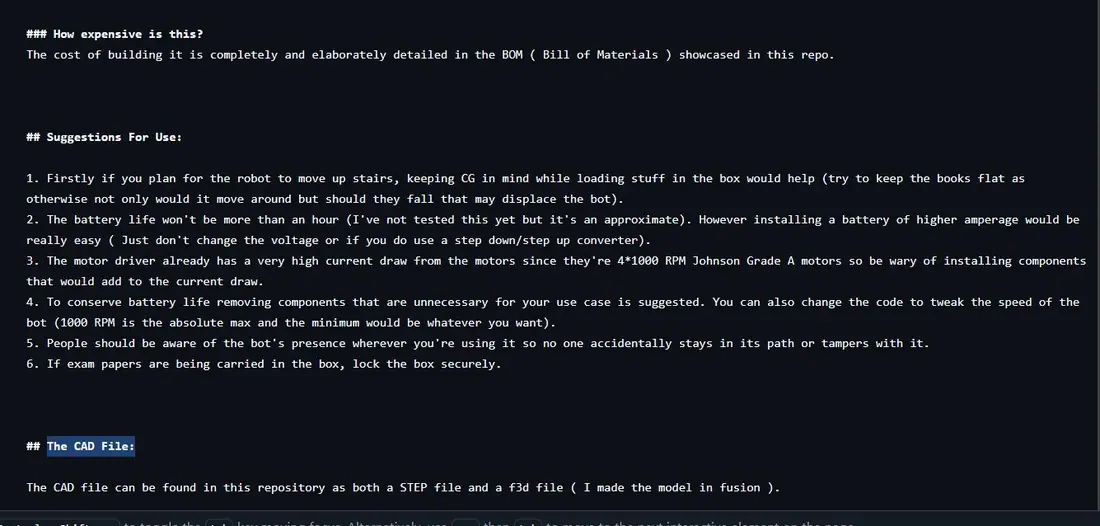
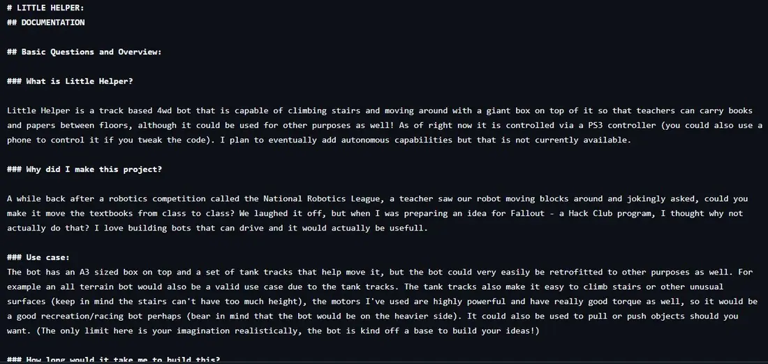
So to start off for the day, I first made a Github repository for my project and started off with the readme for the project. I made the following headings: Basic questions and overview, The CAD file, Suggestions for use. There isn't really that much to talk about. The way I wrote it was by thinking of how project readmes of projects I really admire looked like, and thinking from the perspective of someone who was reading this for the first time in the sense that I had no relation to the project or skills. I tried to think of what I would like to know and in what format.
After I finish all the sections of the readme that I can currently, I'll move on to the schematic diagrams and BOM as well as the code.

Image 1 from devlog #22: GitHub Repo and ReadmeImage 2 from devlog #22: GitHub Repo and ReadmeImage 3 from devlog #22: GitHub Repo and Readme
#23Readme UpdateDOCSJun 12, 2026 · 48min tracked · 1 recording

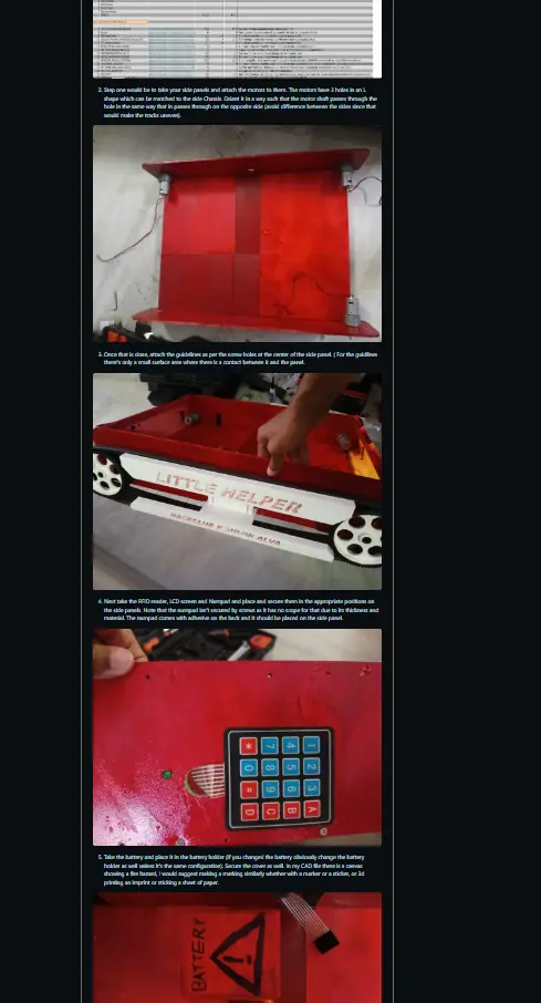
I updated the ReadMe with some more information pertaining to the CAD file, code and I made a complete guide on how to build it as well. I also spoke about what should be changed, and what people can modify if they're making the project on their own. I improved previous headings by filling in the gaps that I realised were present after I started talking about the build. Now anyone can build the project by just getting the materials and sourcing the ReadMe. I have to add a BOM and photos of the CAD model to the repo which I will do next log, and I also realised that I forgot to make the holes and fasteners for the motors to the side panel.

Image 1 from devlog #23: Readme UpdateImage 2 from devlog #23: Readme Update
#24Aesthetic ChangesCADJun 12, 2026 · 2h 2m tracked · 2 recordings

The first thing I did was I fixed some mistakes in the CAD file, to make sure it was perfect, like missing screws, misaligned components and holes, and other tiny details that were messing up the work. Due to the base plate moving around a lot of the screws were misaligned, so I did my best to rectify that. For some reason I couldn't manually move the components because of joints, yet they still got messed up and didn't move with the joint which was interesting. A wire also went straight throw the motor driver so I had to go back and fix that. Another thing I did was make some aesthetic changes, cause I realised that the body could do with some paint work. However, choosing the colours and everything was a bit difficult since I lack any aethetic taste really. The colour options on fusion are a bit lacking as well. I added some more detailing and added a little guy that some people may recognise (SOUUUPPPP!!!) . I tried to make a honeycomb type pattern on the front number plate as well (That proved difficult with the size of the honeycombs and the size of the pattern that I wanted my fusion crashed so yay, luckily this time the recovery file actually worked. So then I made the honeycombs much larger so that it was easier to make). All that just to decide the honeycombs don't look the best and leave only 2.
After this I took some photos to add to the Github repo.
Then I also added the 3d files to the repo. I couldn't figure out how to add folders so that's something I'll figure out later.

Image 1 from devlog #24: Aesthetic ChangesImage 2 from devlog #24: Aesthetic ChangesImage 3 from devlog #24: Aesthetic ChangesImage 4 from devlog #24: Aesthetic Changes
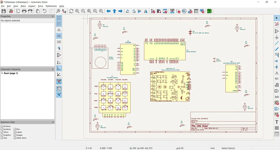
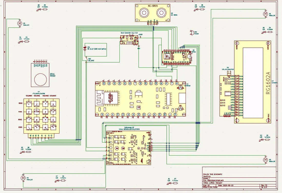
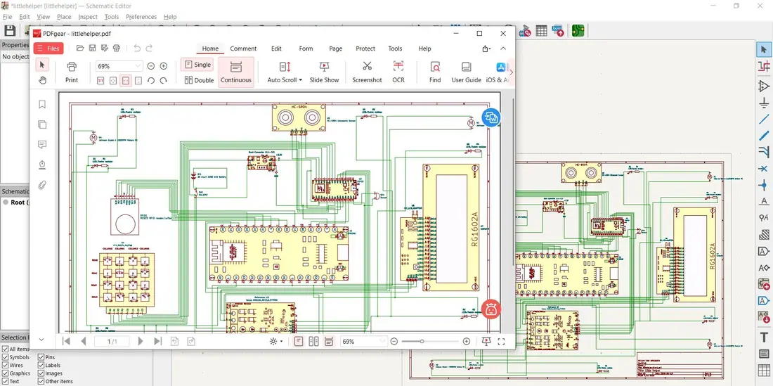
#25★Starting KiCad Electrical SchematicsELECJun 13, 2026 · 2h 11m tracked · 1 recording

Today is the day we finally start out with the schematics!
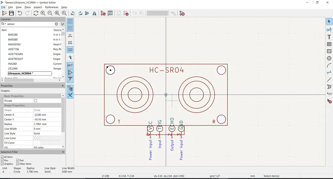
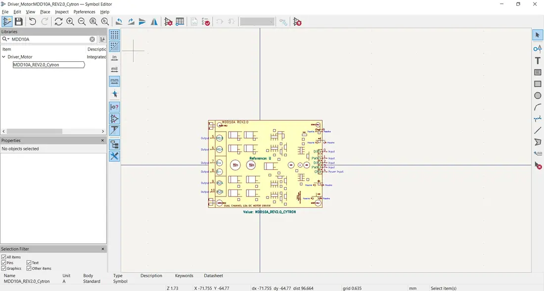
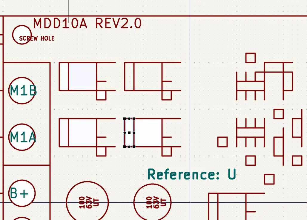
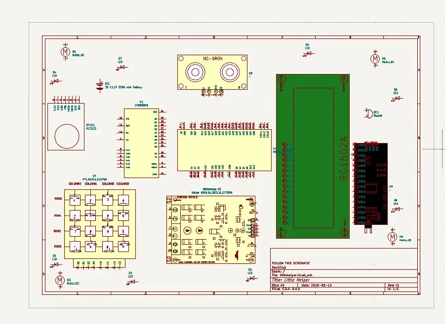
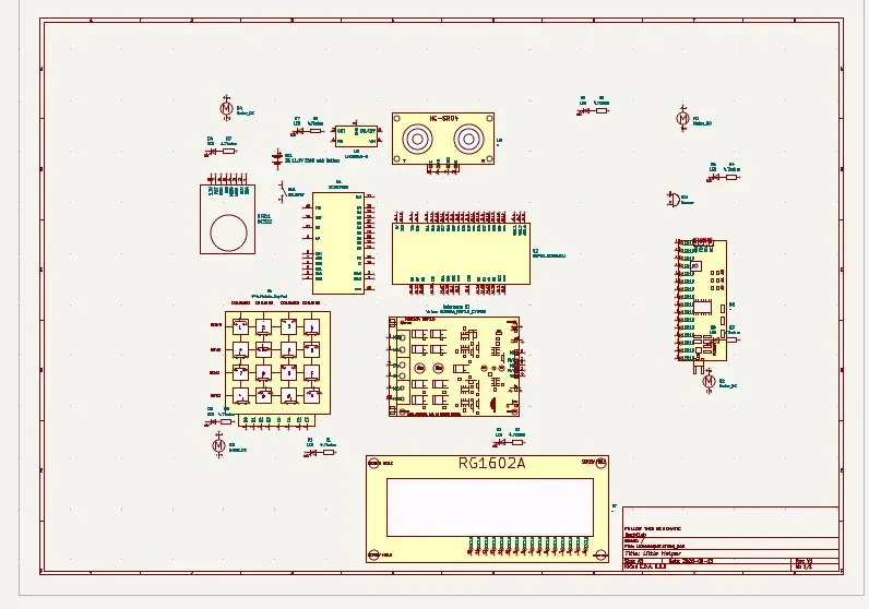
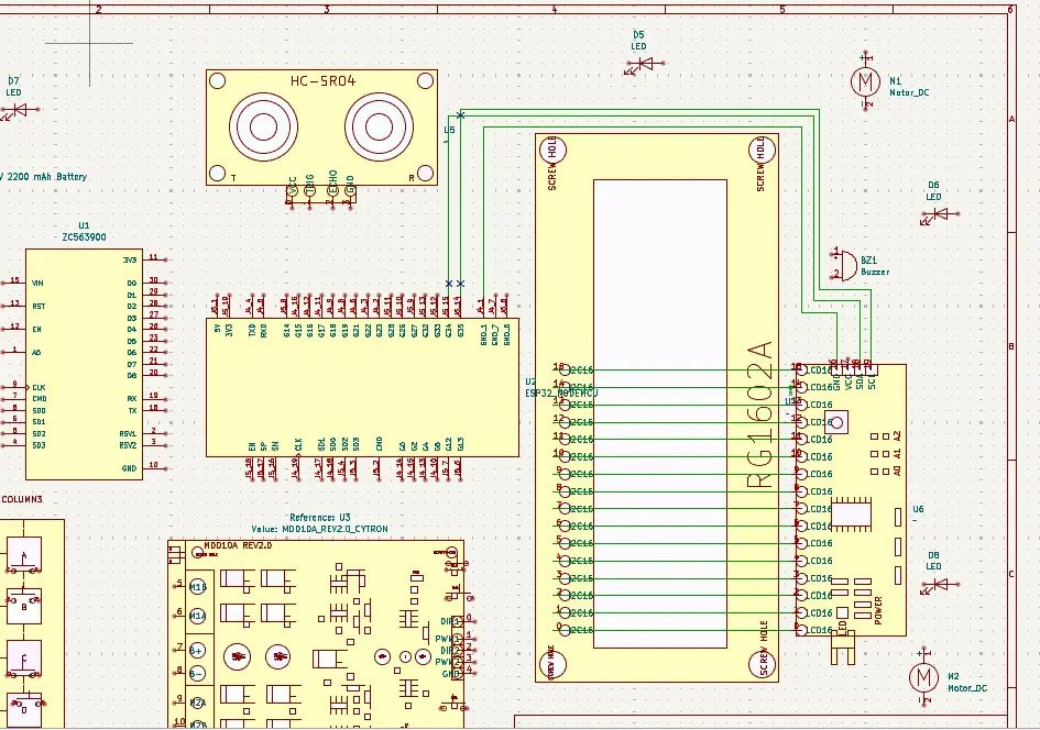
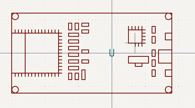
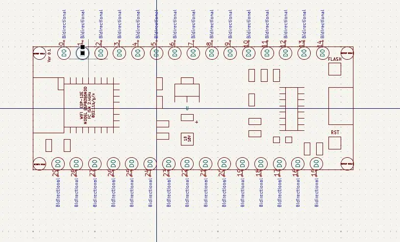
I created the file and then immediately realised I have none of the necessary symbols so I stopped the recording, and just downloaded it all first. The absolute first thing I did was change the autosave time to 3 minutes since I didn't want the same thing as the fusion crashes to happen. I downloaded nodemcu esp32 and esp8266s online as well as the rfid reader and lcd screens. I realised I'd have to custom make the motor driver, I2C adaptor and the rest I could just add generic components. I hope lookout doesn't capture audio cause my spotify wasn't working and I started singing to myself instead. For custom making the symbols for some parts, luckily I had the actual components on hand. Unfortunately, this is my first time using Kicad so the quality of work was, let's just say lacking. I have genuinely no idea what I'm doing and I'm cooking up some nonsensical looking stuff, but honestly this is the extent of my ability. Hopefully I learn through this. I tried my best to just make it look exactly like what was right infront of me, but one mistake I made was not making the symbol big enough which ended up with some components on the board of various sizes looking exactly the same. Like a genius I made the pins manually not realising you should do that with the pin add command, after I inserted all the pins I realised that by convention they should be inverted. The learning curve for this part is really steep to say the least. I tried to keep the placement of the symbols as accurate as I could to what it would actually be. After I moved all the stuff into the main file (Except the I2C, I realised I imported the wrong LED screen as well so I have to custom make that too) , I stopped recording for the day to go take a break.

Image 1 from devlog #25: Starting KiCad Electrical SchematicsImage 2 from devlog #25: Starting KiCad Electrical SchematicsImage 3 from devlog #25: Starting KiCad Electrical SchematicsImage 4 from devlog #25: Starting KiCad Electrical Schematics
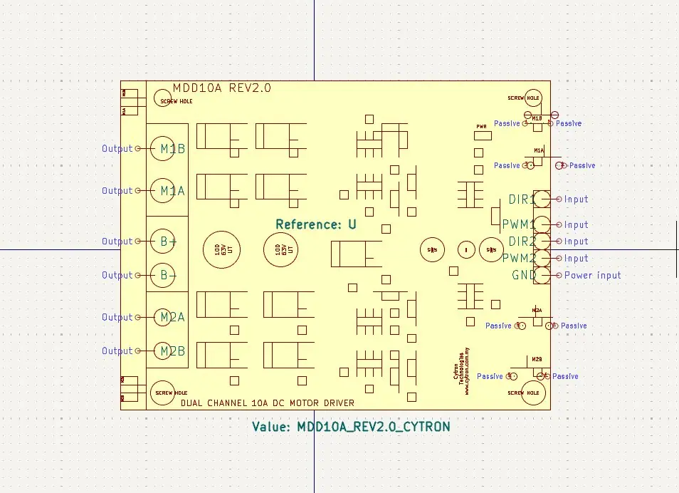
#26LCD Schem and ColourELECJun 13, 2026 · 56min tracked · 1 recording

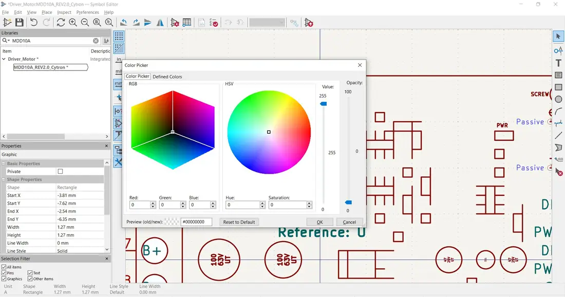
I made the I2C Adapter and the LCD screen's schematic diagram. I realised though that I had lost my LCD screen which was a little unfortunate. While I was making the schematic, I realised, why use yellow as the background colour instead of the actual colour? I tried to also get the internal parts to have their own colour, I didnt realise that it overlays the more intense colour over it. After importing the symbols in though I realised that it looked horrendous and the uniformity was why it was all yellow. My scaling may be a bit odd though for the project the component sizes really aren't accurate, but since they're 3d modeled it doesn't really matter since I know the space won't be an issue. My perfectionism made me take a really long time just to make all the internal components white to distinguish it from the rest of the body. Atleast all the symbols are imported now. I came to the unfortunate conclusion that I was wasting so much time in colour picker when I could have just picked the defined colour from the next tab. I also love saving the file and not seeing it lag out like the CAD files.

Image 1 from devlog #26: LCD Schem and ColourImage 2 from devlog #26: LCD Schem and ColourImage 3 from devlog #26: LCD Schem and ColourImage 4 from devlog #26: LCD Schem and Colour
#27Wiring the Schematic - a poor AttemptELECJun 13, 2026 · 1h 5m tracked · 1 recording

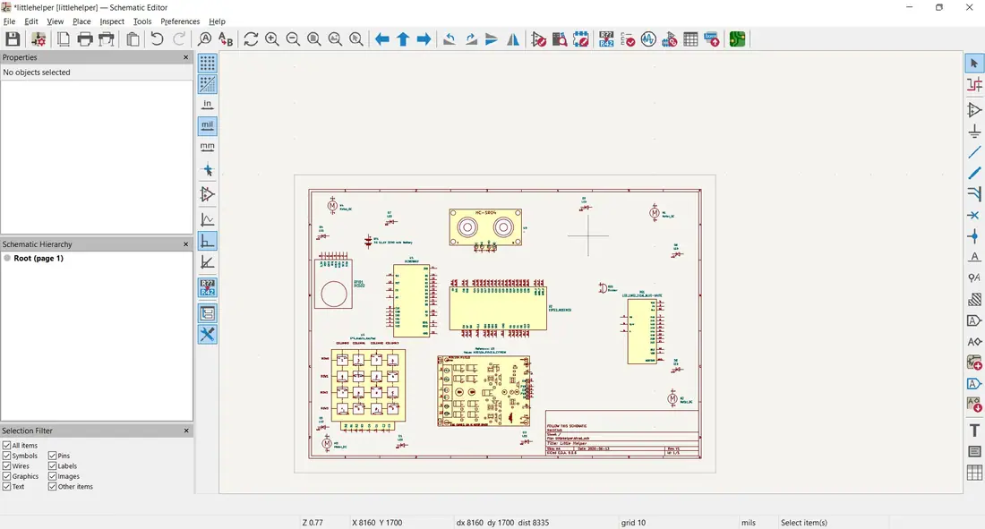
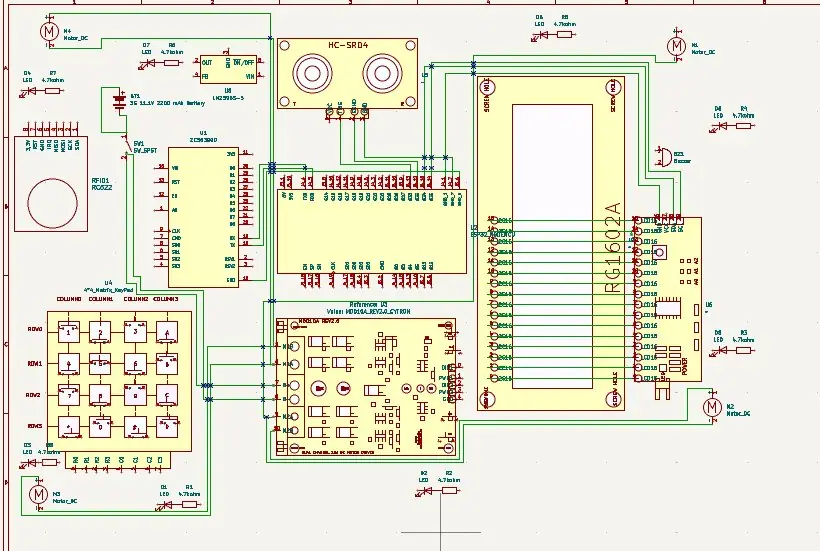
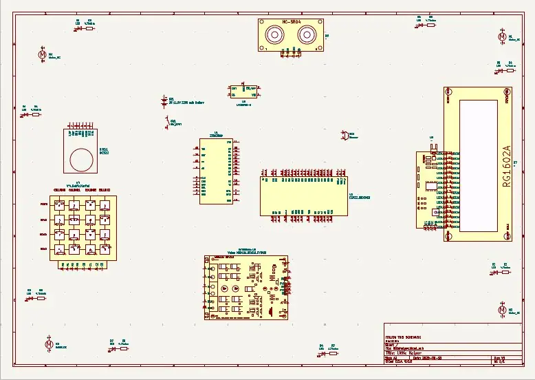
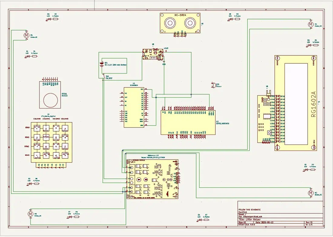
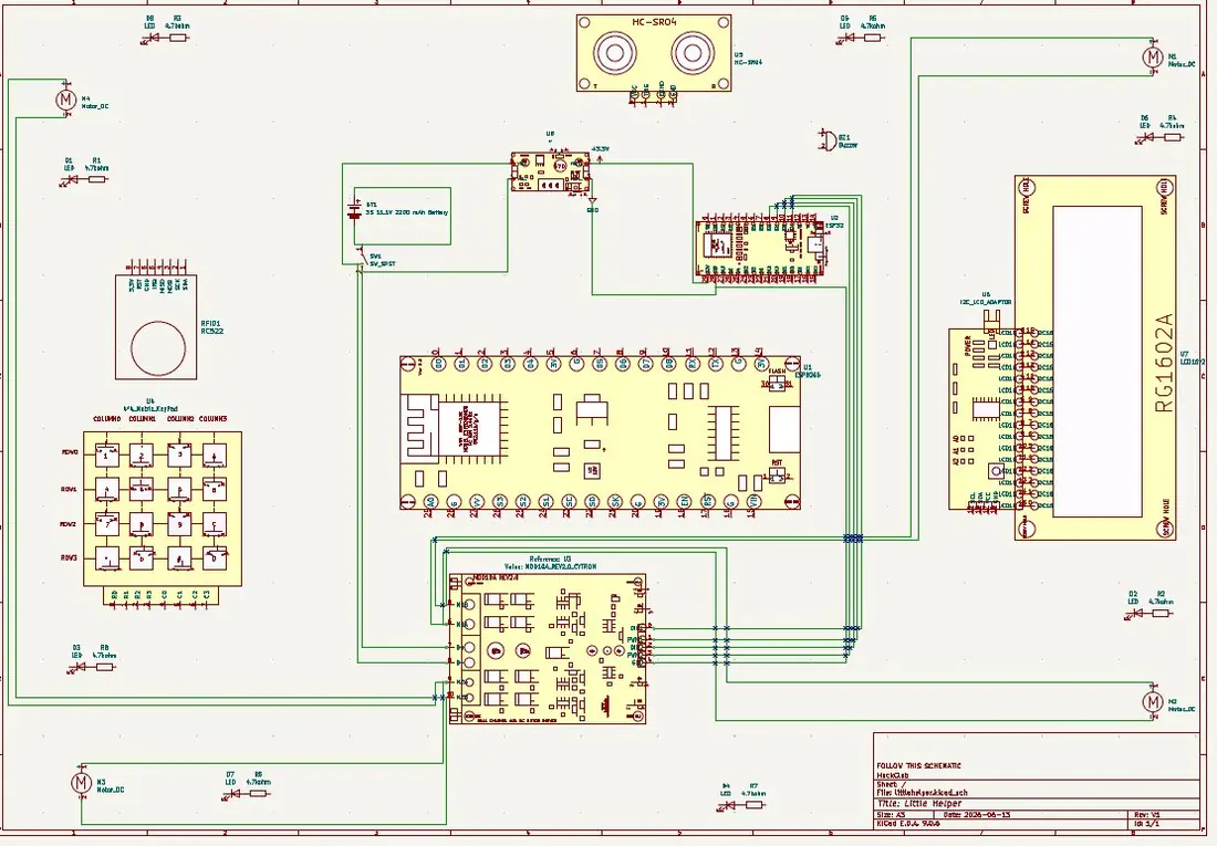
I started wiring the components together, I tried to follow the wiring from the CAD, but some components are slightly innacurate and I also realised that my ESP32 was a WROOM32 in the CAD and a NodeMCU one in the schematic, good thing I added the don't follow the CAD wiring and only use as a reference in the README.md I guess. I'm doing my best to learn standard practise and not just do whatever I want, but having zero knowledge, it's a bit hard. The CAD is still really usefull though, since it saves me quite a lot of thinking cause some stuff is already planned out, and I know how feasible it would be. Yet despite all that CAD work, I made some very very bad errors particularly I didn't realise that my motor driver doesn't have a 5v out pin, which is very problematic for obvious reasons. So now I need to go and buy a buck converter as well for this project just to be able to connect to my esps. My knowledge of diagrams is so limited I didn't even know what switch to use. The file started getting too close without even 1/4th of the wires needed so I had to change the configuration to an A3 sheet and now I have to move all the components one by one. Which is a process I started but didn't finish. In this log though I managed a decent amount of wiring, though it will all dissapear now that I have to delete it all and move everything. I did figure out the basic logic I would need for the buck converter though.

Image 1 from devlog #27: Wiring the Schematic - a poor AttemptImage 2 from devlog #27: Wiring the Schematic - a poor AttemptImage 3 from devlog #27: Wiring the Schematic - a poor AttemptImage 4 from devlog #27: Wiring the Schematic - a poor Attempt
#28Figuring out VoltagesELECJun 14, 2026 · 1h 15m tracked · 1 recording

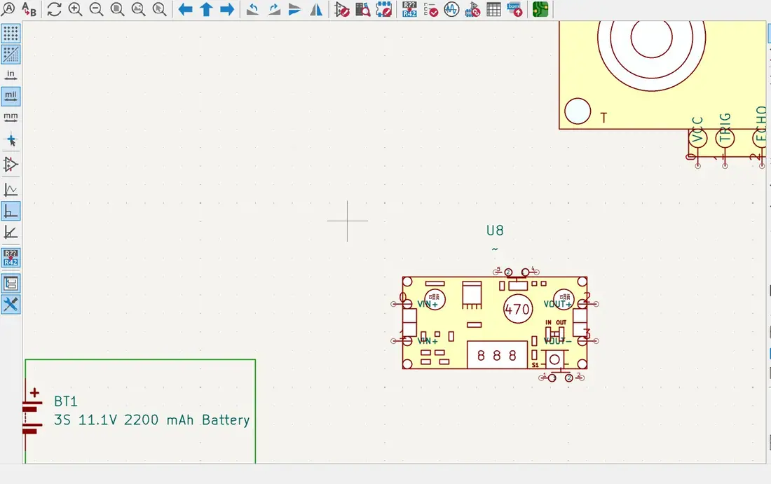
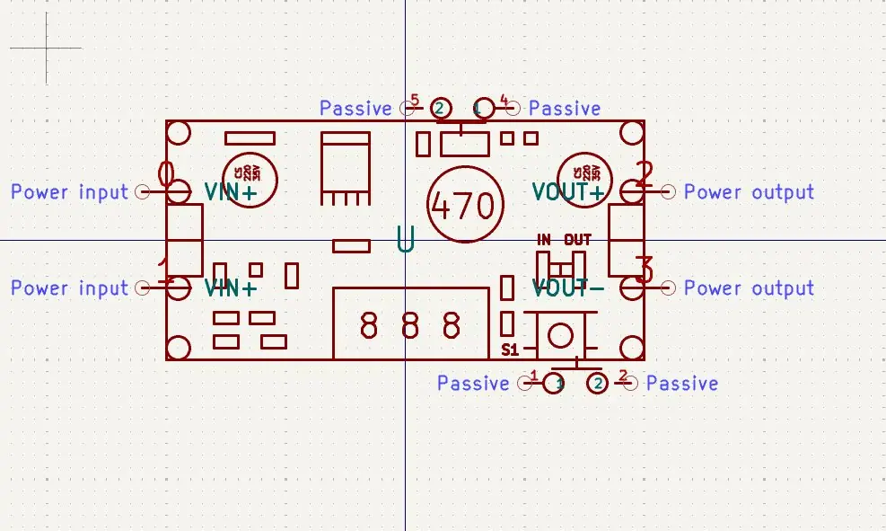
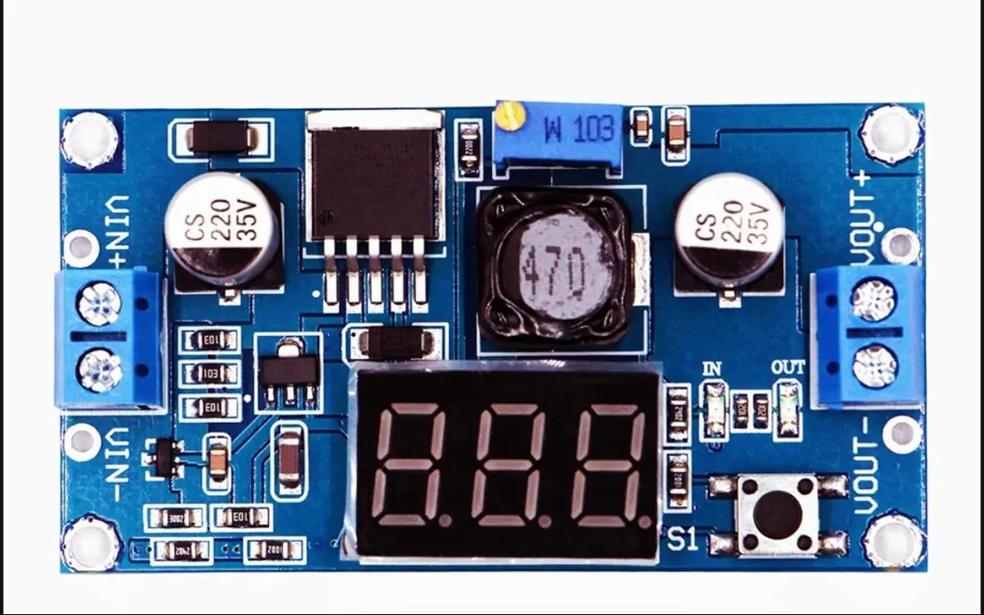
Started out by optimising the placement of symbols in the schematic to make the wires look tidy. I almost miscalculated the buck converter and set it to 5V to fry my esps. I realised I need 1 converter to 5V and 1 to get me to 3.3V. Then I realised I only need to step it down to 3.3V and I can use the ESP's VIN pins for the 5V outputs, and that way I'm maintaining uniform logic as well. I realised that converting this voltage isn't as easy as I thought. But then I found a voltage converter that while slightly more expensive would be way safer than my nonsense. I just had to make another custom symbol for that. I tried to even add in the LEDS in the buck converter to the symbol but it wouldn't fit. At this point I've rethought and redone the wiring like 5 times, so the all in one buck converter seems like a great option since I don't want to fry my ESPs and have to buy new ones. While the buck converter and logic has been mostly fixed, I still have to get around to doing the wiring all over again.

Image 1 from devlog #28: Figuring out VoltagesImage 2 from devlog #28: Figuring out VoltagesImage 3 from devlog #28: Figuring out VoltagesImage 4 from devlog #28: Figuring out Voltages
#29Accurate ESPS and WiringELECJun 14, 2026 · 1h 21m tracked · 1 recording

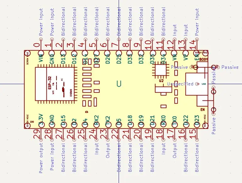
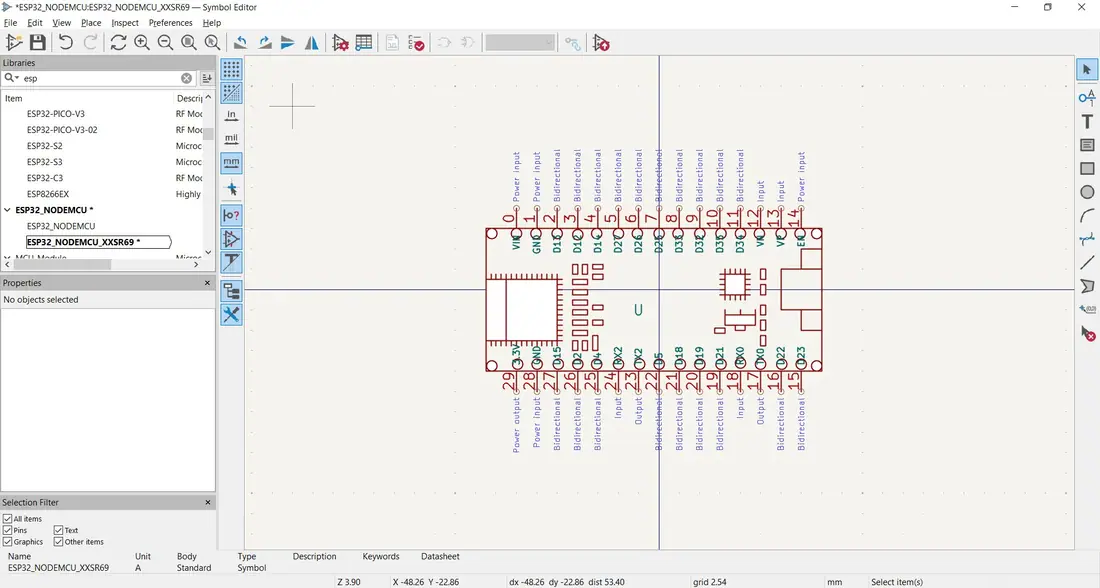
Started off with the wiring, and the new buck converter really simplified a lot of the work as well. Having the increased page size also gave me a lot of room to work with. With the motor driver I'm using, both the motors on one side connect to the same pinouts. The NODEMCU ESP32 diagram does differ slightly from the one I have, which I realised after wiring once again when I actually cross referenced it. So I once again custom made the symbol for it and now I have to redo the wiring. The way stuff was arranged in the symbol kept stopping me from being able to fill in the internal circles which really bugged me. Having a timeline like in fusion would be so helpful.

Image 1 from devlog #29: Accurate ESPS and WiringImage 2 from devlog #29: Accurate ESPS and WiringImage 3 from devlog #29: Accurate ESPS and WiringImage 4 from devlog #29: Accurate ESPS and Wiring
#30Better ESP 8266ELECJun 14, 2026 · 43min tracked · 1 recording

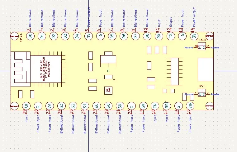
Realised even my ESP8266 differs from the one in the symbol, I think NODEMCU makes a few different versions, so I just made my own symbol again. I'm spending so much time on the symbols at this point but I'd rather be safe than sorry. As always having the physical component to visually see and draw out is so helpful. The alignment of the pins and the circles came out perfectly this time.
I realised that filling in all the internal things white wasn't perfectionism it was stupidity since I could have just made a white one then duplicated it, but too late now. The ESP8266 was perfect until I realised I accidentally made it multiple time the size it should have been.

Image 1 from devlog #30: Better ESP 8266Image 2 from devlog #30: Better ESP 8266Image 3 from devlog #30: Better ESP 8266Image 4 from devlog #30: Better ESP 8266
#31Wiring Again and Some False Standard PracticeELECJun 15, 2026 · 52min tracked · 1 recording

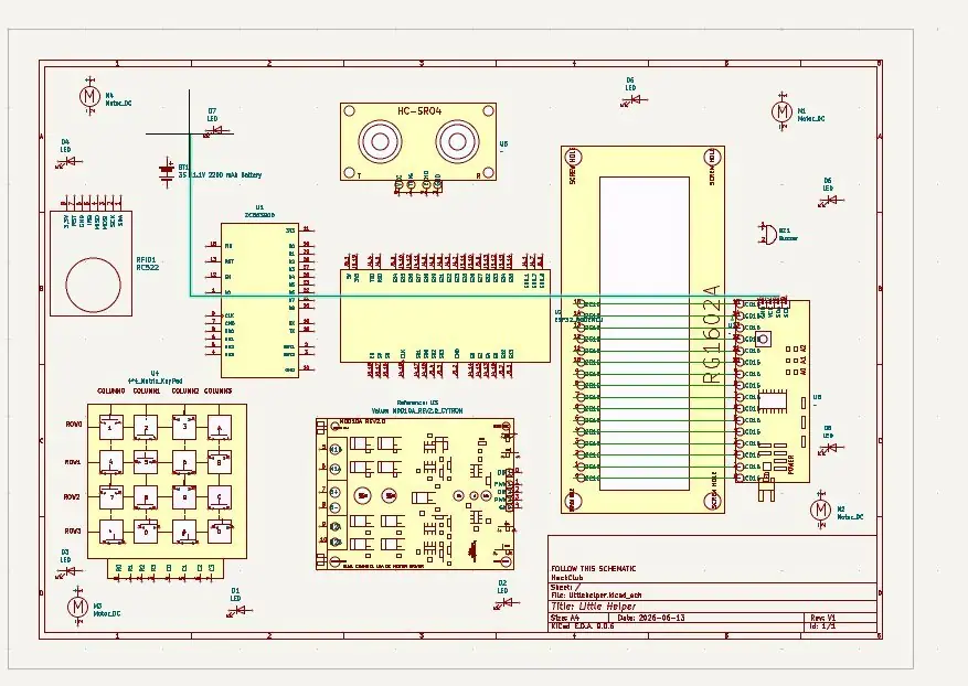
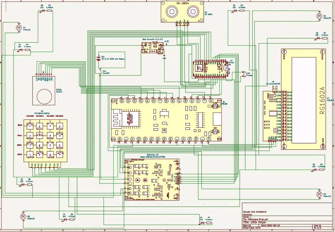
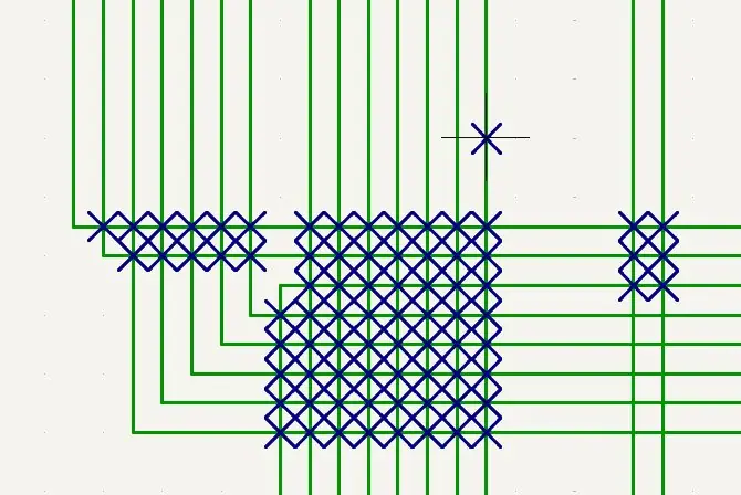
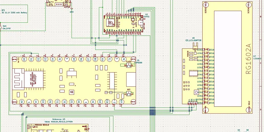
I continued with the wiring, connected the ESPs together and the numpad to the esp. My wiring in the CAD and the schem is different, but it's written in the readme that the schematic should exclusively be followed, and regardless the difference can be easily tweaked in the code if someone follows something different. The I2C on my LCD saves me from having to use a logic shifter to connect it to my ESP. I connected the LCD's I2C to the ESP8266. I tried to use the default SCL and SDA pins, but again that would just be a quick code debug and fix. I realised I was placing no connect flags everywhere there was a wire without a junction which apparently isn't what you're supposed to do, so I had to go delete all of them.I mostly finished the wiring, so I'll probably be moving to the code soon.

Image 1 from devlog #31: Wiring Again and Some False Standard PracticeImage 2 from devlog #31: Wiring Again and Some False Standard PracticeImage 3 from devlog #31: Wiring Again and Some False Standard PracticeImage 4 from devlog #31: Wiring Again and Some False Standard Practice
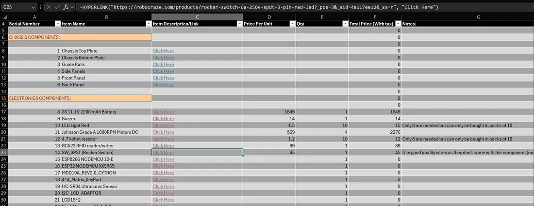
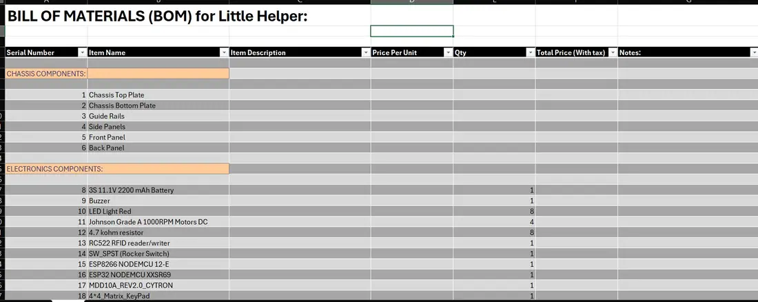
#32Repo Update and BOMJun 15, 2026 · 1h 8m tracked · 1 recording

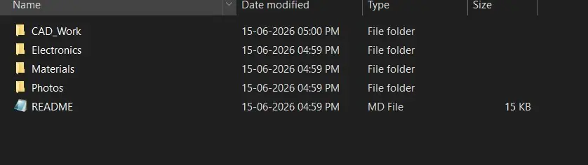
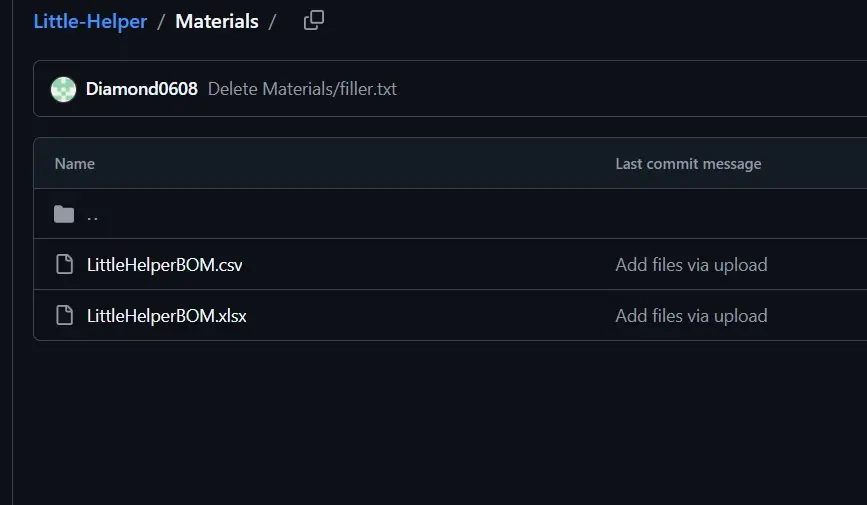
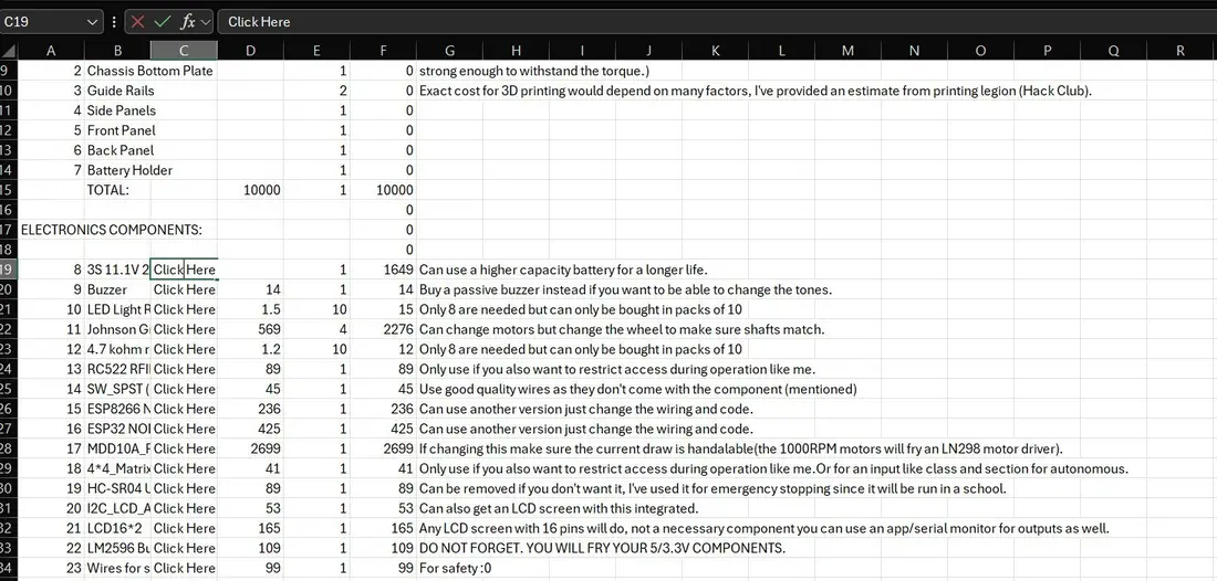
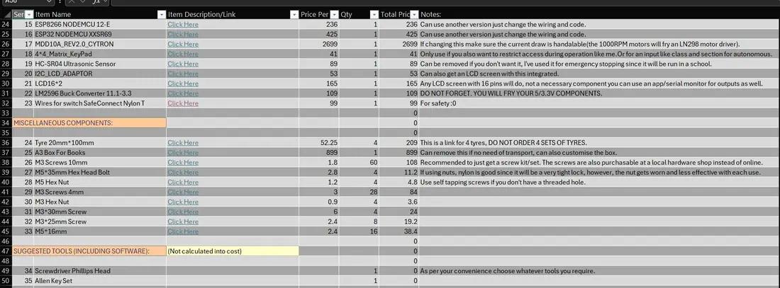
I spent an embarrasing amount of time trying to create a folder in GitHub since I'm not really familiar with it. Once I did that, I organised my files into folders. My lack of knowledge is genuinely embarrasing, but I guess we all have to start somewhere. I also exported the BOM from KiCad to use as a starting point as well as the schematic as a pdf and put it in the GitHub. I managed to add the full 3d files to GitHub as well instead of just the links using the app. I then got to work on the BOM. I also took the BOM from fusion to help. I'll update the ReadMe with this as well as more detailed wiring instructions as well. I have some more work on the BOM to do, then after the ReadMe I'll get to work on the code.

Image 1 from devlog #32: Repo Update and BOMImage 2 from devlog #32: Repo Update and BOMImage 3 from devlog #32: Repo Update and BOMImage 4 from devlog #32: Repo Update and BOM
#33Completing BOMDOCSJun 15, 2026 · 58min tracked · 1 recording

Continued with the BOM, added pricing and links to the product and also added notes mostly pertaining to whether people can not use that component and customise it. When I exported to CSV, I lost not only all my formatting but the hyperlinks, so I guess it's a good thing I caught that in time. I decided to put an xlsx as well as a csv just incase. I guess now it's time to move onto the firmware.

Image 1 from devlog #33: Completing BOMImage 2 from devlog #33: Completing BOMImage 3 from devlog #33: Completing BOM
#34Starting off With FirmwareCODEJun 16, 2026 · 57min tracked · 1 recording

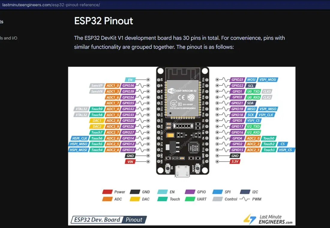
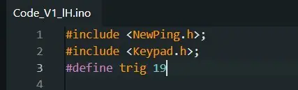
Started off with the firmware today, but first I included the modules needed for the ESP32 components and then cross referenced each of my pins on the ESP32 with an online pinout version so I could check the GPIO pin numbers to be able to code it. Luckily most of the pins correspond to their Digital pin numbers so for those pins it was quite easy to define variables. Hopefully messed up pin numbering or functions won't be too hard to fix though. My lack of coding ability without AI though is making progress really difficult. I did have to use gemini to make it teach me since I was really confused. I'm trying my hardest to not use googled/ai generated code and learn it completely but god is progress going slow.

Image 1 from devlog #34: Starting off With FirmwareImage 2 from devlog #34: Starting off With Firmware

Part 2: Physical Build

Aug 15 to Aug 19, 2026 · 36 devlogs

Printing, gluing, painting, wiring and debugging the real robot. Written up in batches, so the work time is in each title.

#35Supports and GlueAug 15, 2026

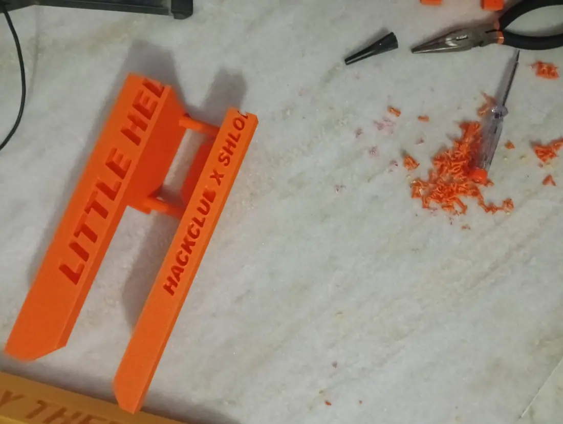
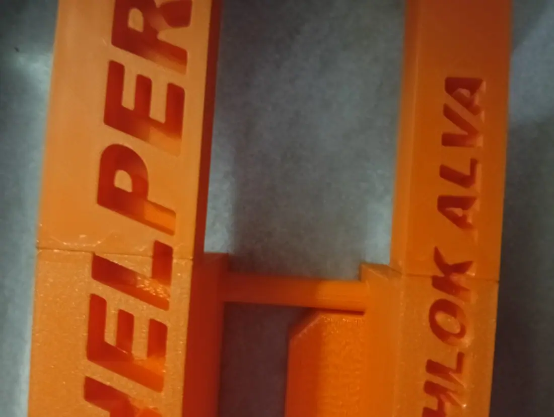
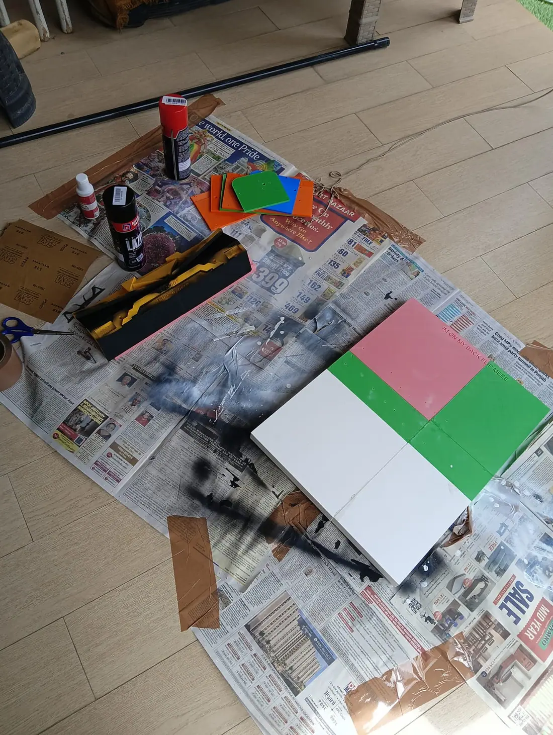
I worked on removing the supports from all the 3d printed parts which went decently well, however the small texts and the pictures of soup didnt end up coming out so great. After that I used Metlock 743 to glue the 3d parts that should be one piece together (which was nerve wracking since the adhesive is an instant bond, where the plastic melts together which means if i mess up theres no fixing it it would be like trying to remove a part that was printed as a single piece.

Image 1 from devlog #35: Supports and GlueImage 2 from devlog #35: Supports and GlueImage 3 from devlog #35: Supports and Glue
#36More gluingAug 15, 2026

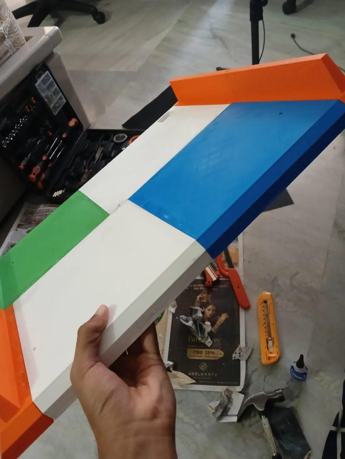
I glued the guiderail parts together , and interestingly for some reason the orange parts with pla pro instead of pla+ needed me to sand down the parts before it would actually stick together. Unfortunately I also keep gluing my hands and my floor so thats great.

Image 1 from devlog #36: More gluingImage 2 from devlog #36: More gluingImage 3 from devlog #36: More gluingImage 4 from devlog #36: More gluing
#37Gluing AgainAug 15, 2026

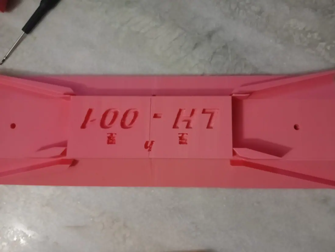
I started on making the top plate a complete piece, I realised I could use the adhesive as a primer since it melts the plastic making it easier to sand, so I applied metlock wiped it off then sanded and glued the parts again. The parts have inserts to join them together but printing mistakes and bad tolerances mean I have to either manually trim the the inserts or cut them off entirely. There is a decent gap between the components with the inserts now because of that but it is still firmly held together.

Image 1 from devlog #37: Gluing AgainImage 2 from devlog #37: Gluing AgainImage 3 from devlog #37: Gluing AgainImage 4 from devlog #37: Gluing Again
#38Top Chassis GluedAug 15, 2026

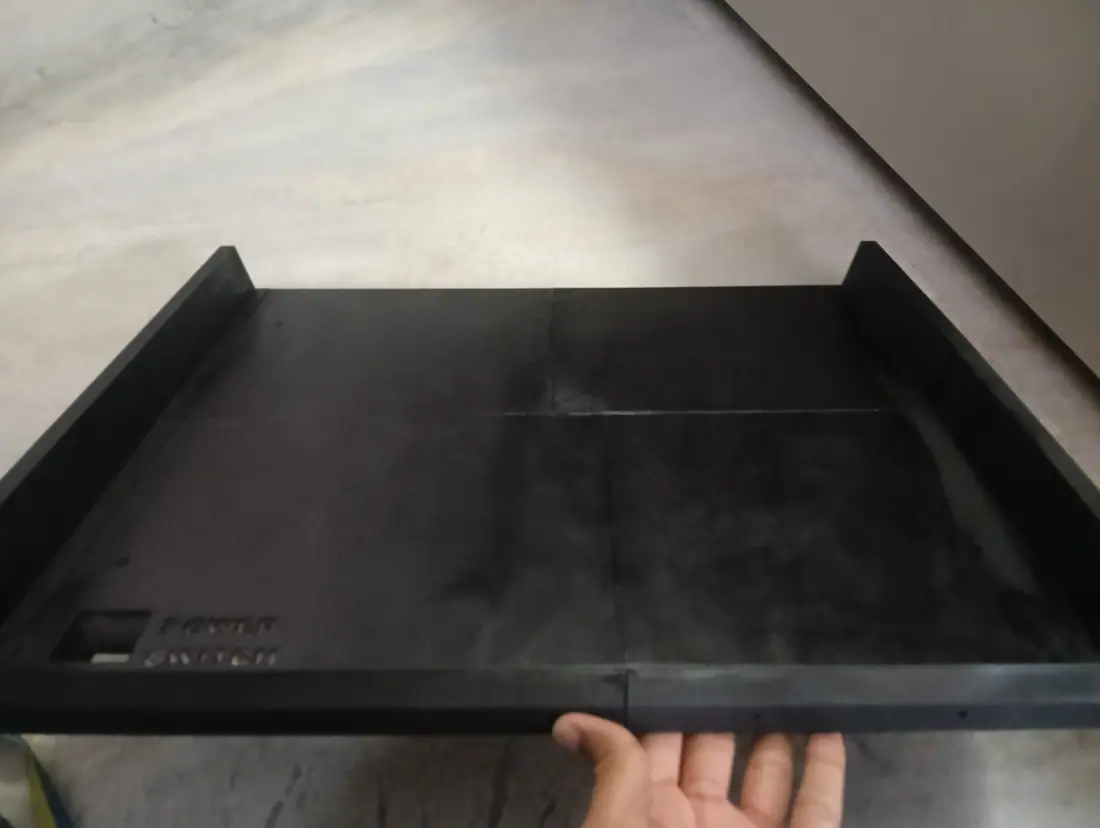
I finished gluing the top of the chassis and luckily all the pieces fit together perfectly (after I sawed off the inserts though). The top piece is not only HUGE its heavy despite its low infill, I think I may need to change the design of the side panels for it to be able to bare the weight but lets see.

Image 1 from devlog #38: Top Chassis GluedImage 2 from devlog #38: Top Chassis GluedImage 3 from devlog #38: Top Chassis GluedImage 4 from devlog #38: Top Chassis Glued
#39SPRAY PAINTINGGGG and gluingAug 15, 2026

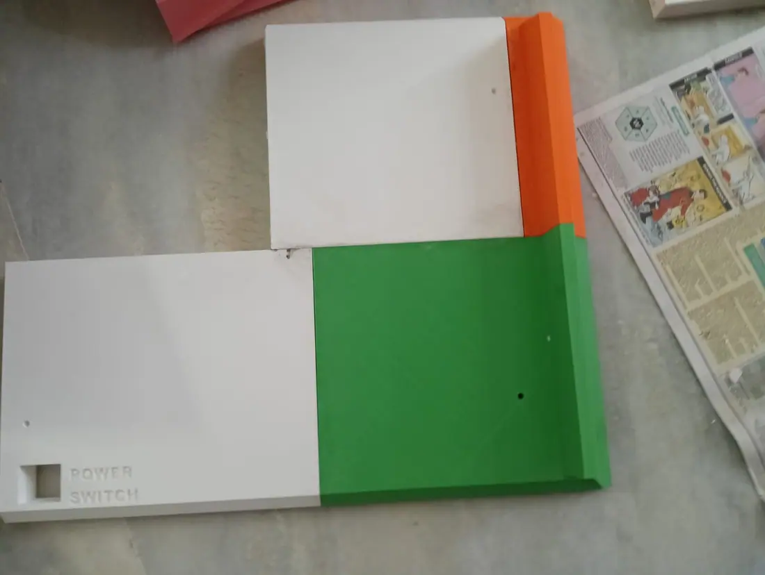
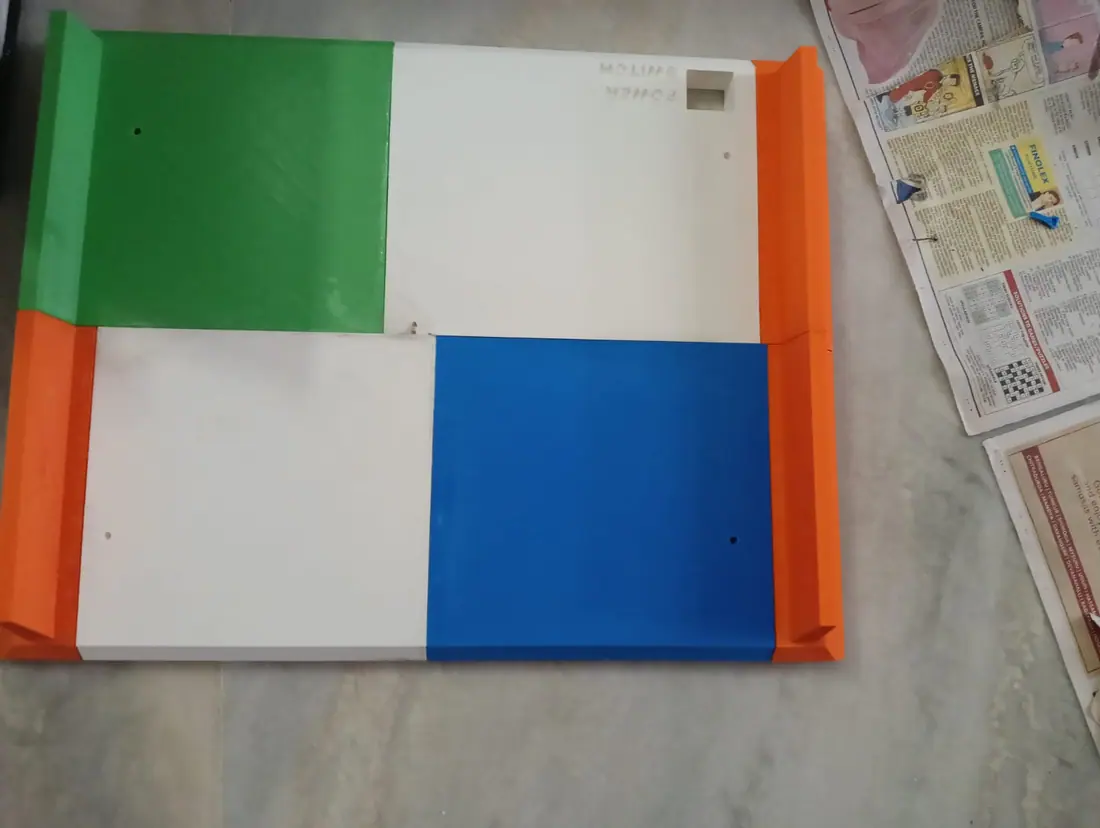
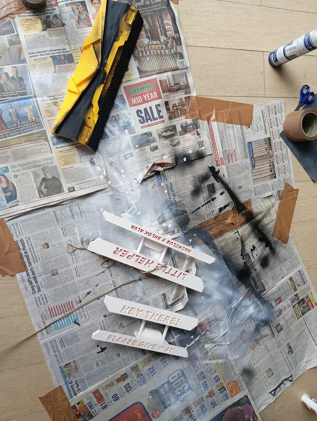
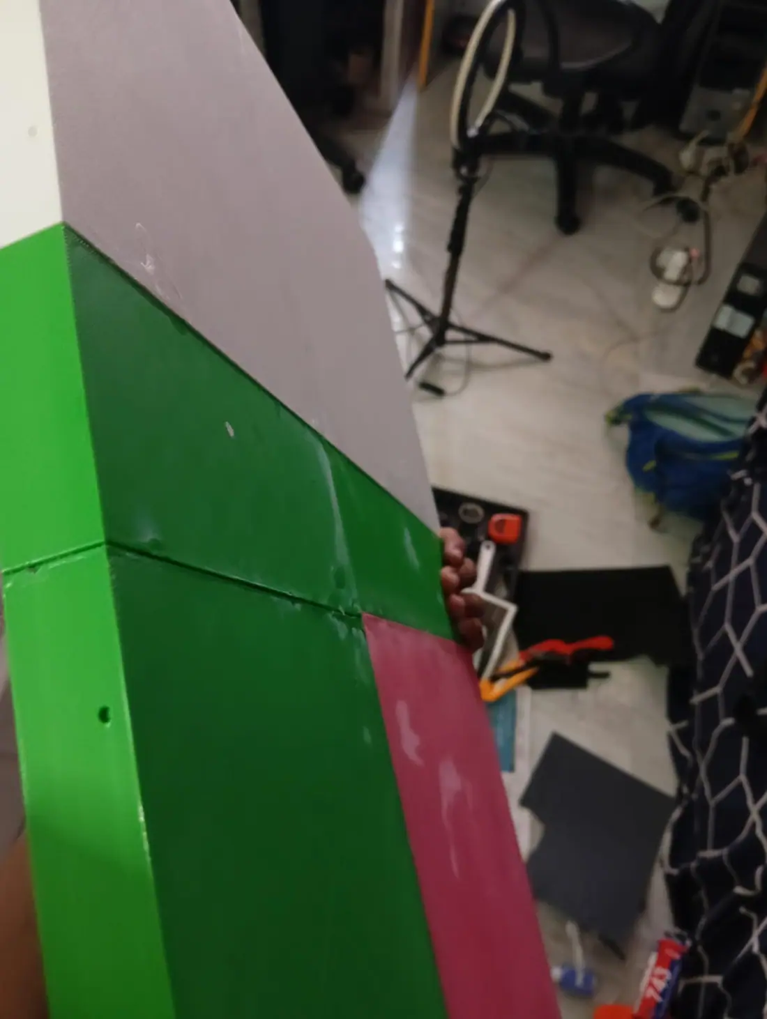
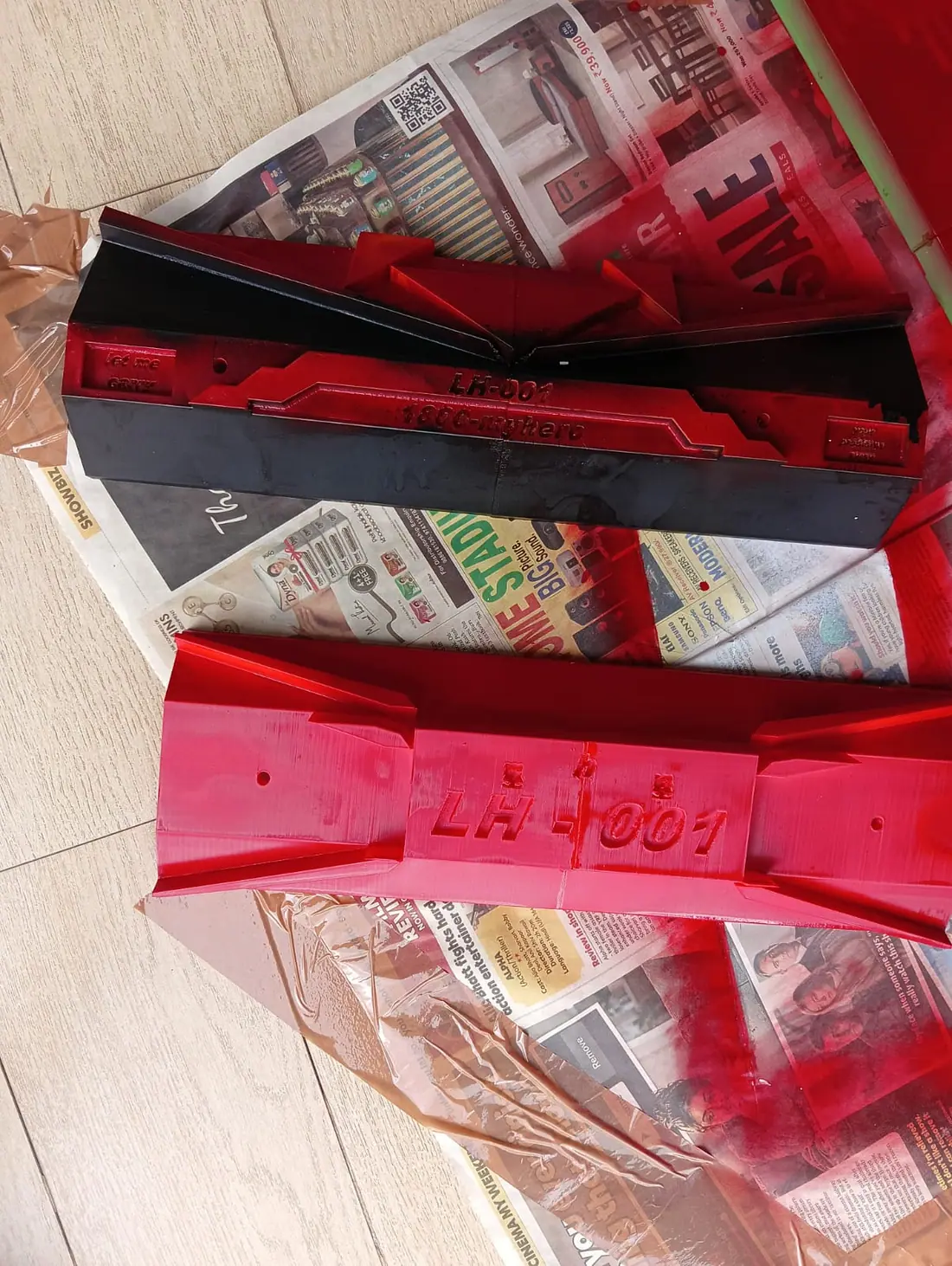
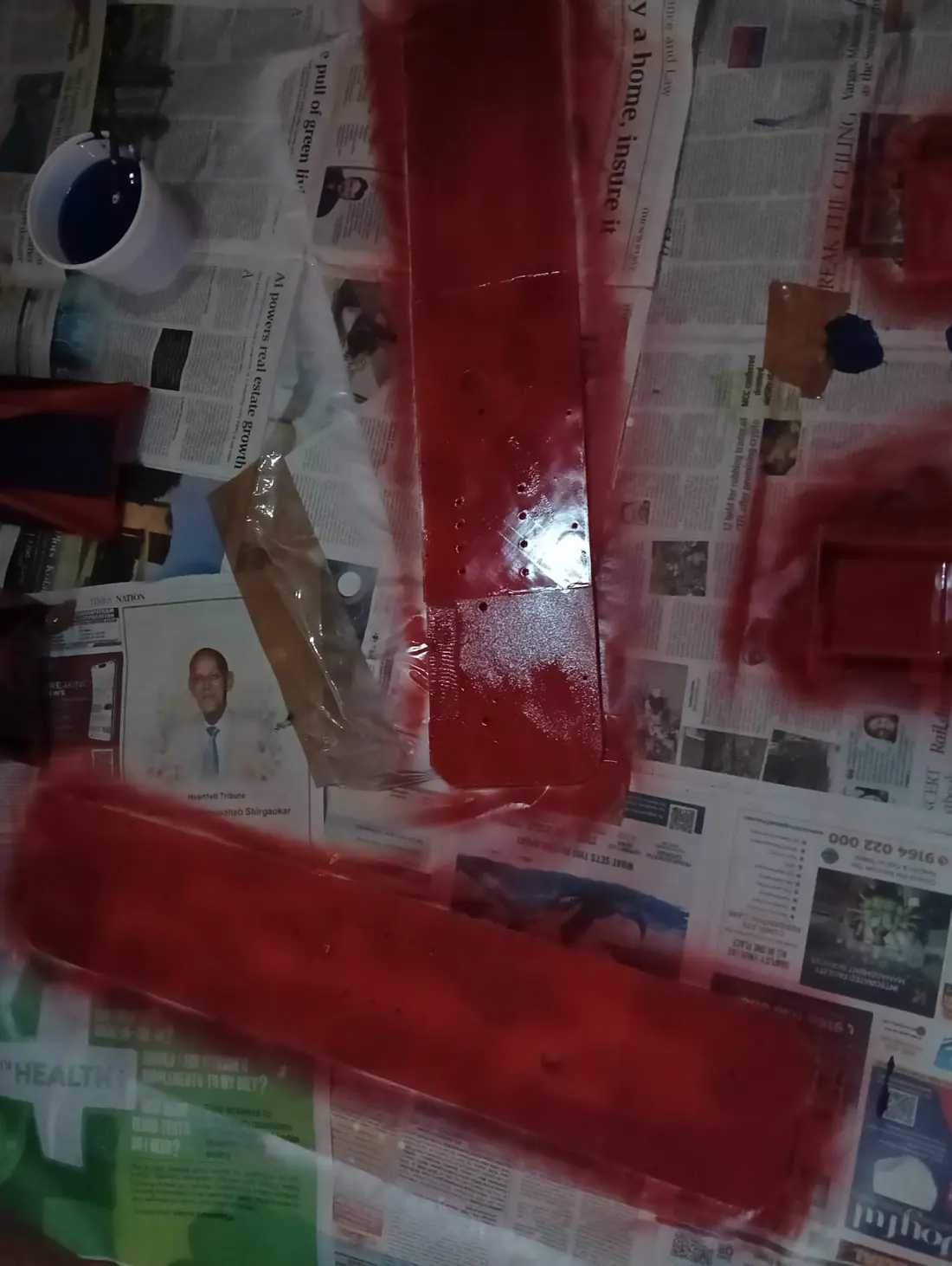
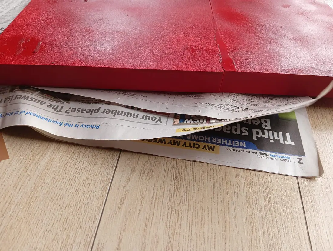
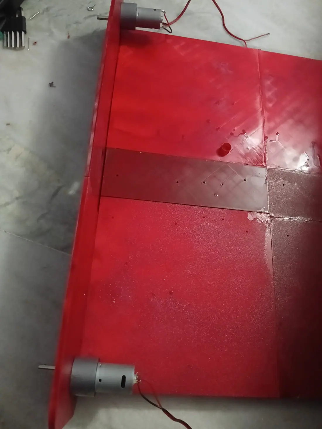
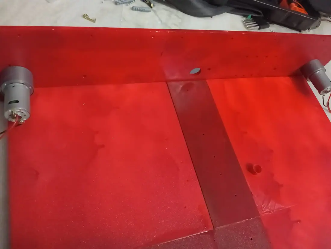
I started the paint job by sanding the top of the chassis and then spray painting it black, I then spray painted the guidelines white and parts of the back plate black. I then went back to my endless job of sawing off the inserts and sanding and priming and gluing the pieces together. (Glued 2 of the back plates together before annoying my brother with the noise of the sawing and moving to my terrace which shall be the next devlog).

Image 1 from devlog #39: SPRAY PAINTINGGGG and gluingImage 2 from devlog #39: SPRAY PAINTINGGGG and gluingImage 3 from devlog #39: SPRAY PAINTINGGGG and gluingImage 4 from devlog #39: SPRAY PAINTINGGGG and gluing
#40Bottom chassis finishedAug 15, 2026

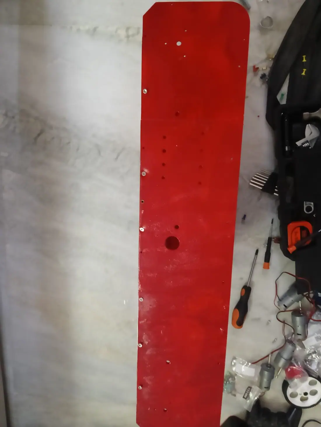
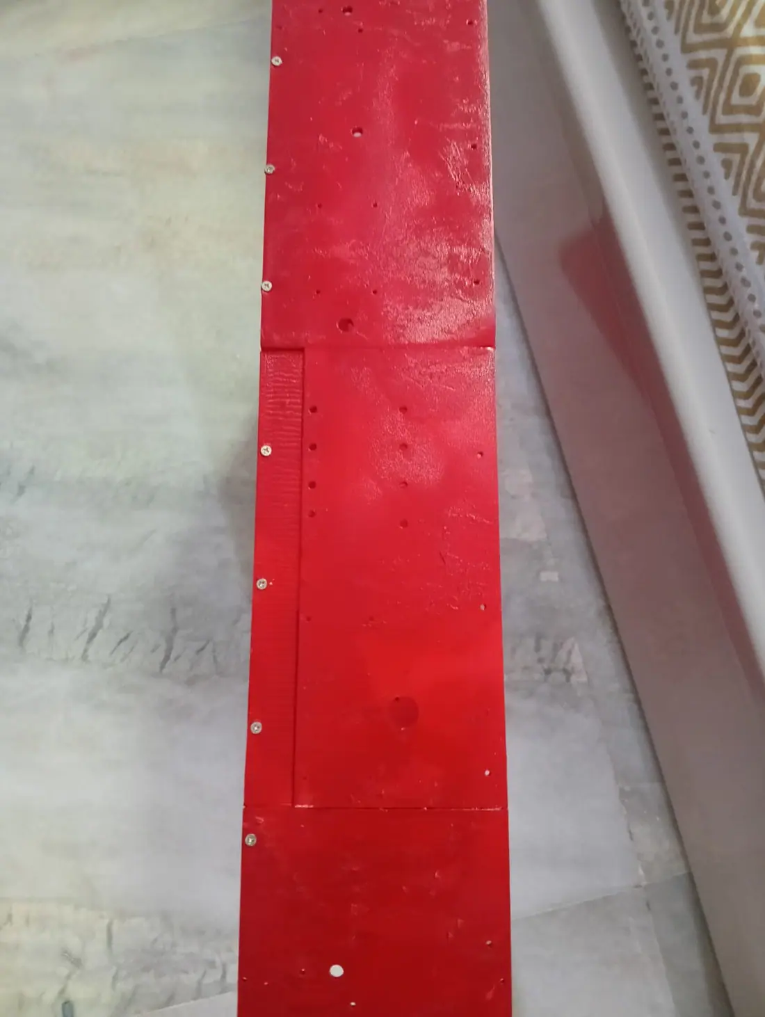
I finished gluing together the bottom chassis into 1 solid plate, now once I paint that red the top and bottom plates will be completely finished.

Image 1 from devlog #40: Bottom chassis finishedImage 2 from devlog #40: Bottom chassis finishedImage 3 from devlog #40: Bottom chassis finishedImage 4 from devlog #40: Bottom chassis finished
#41Painting some more (30mins)Aug 15, 2026

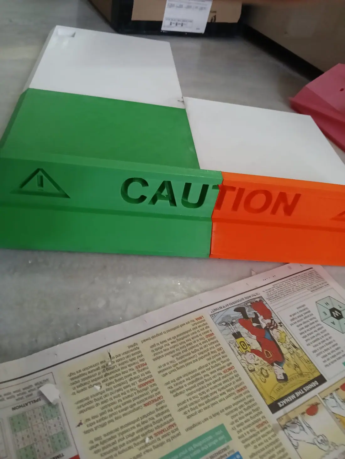
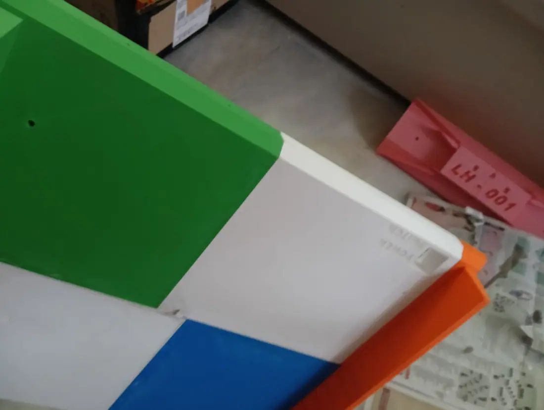
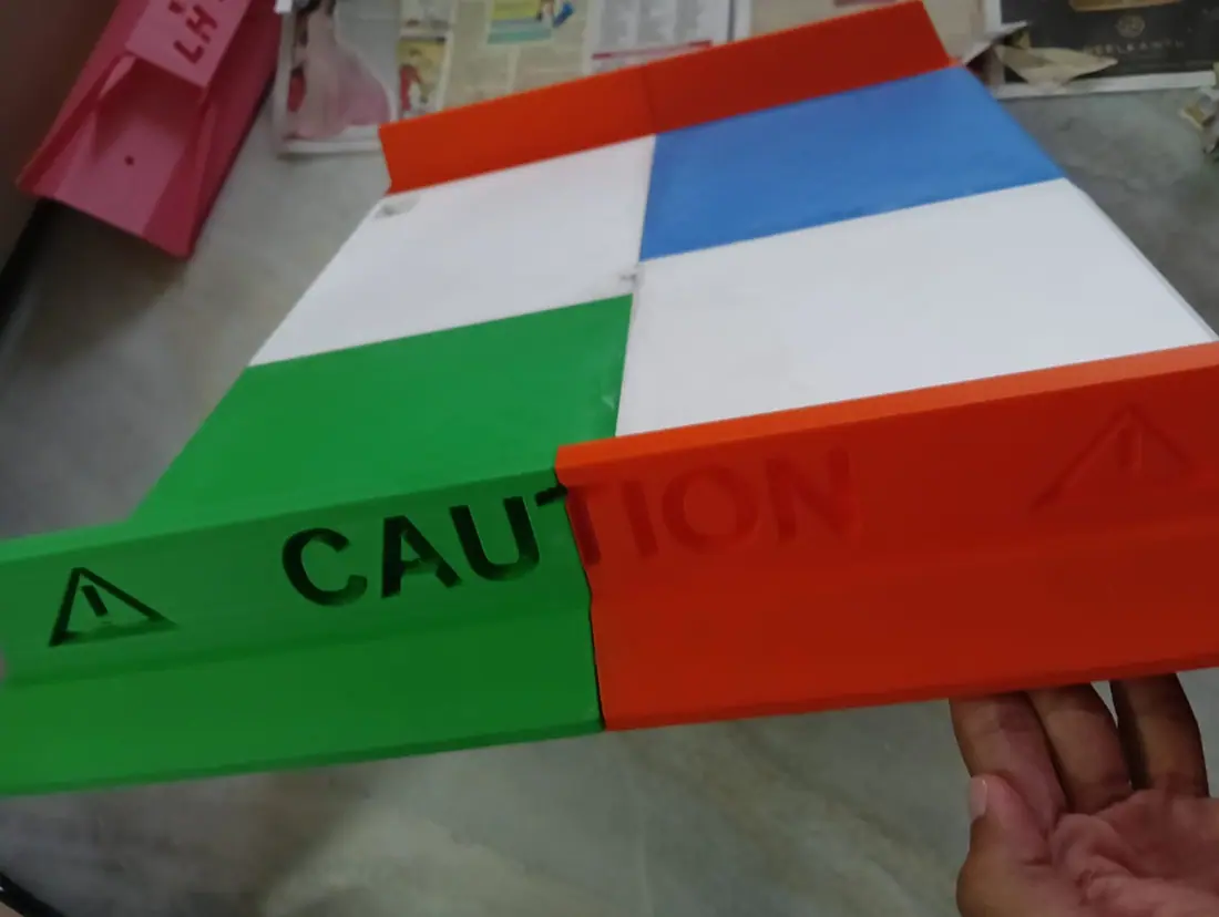
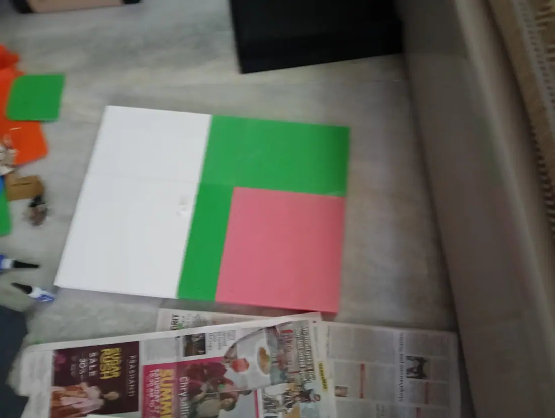
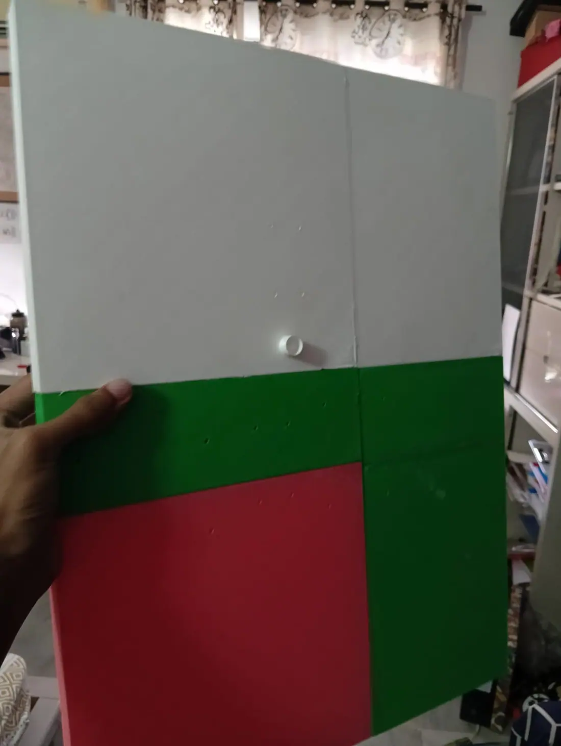
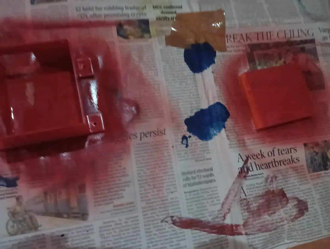
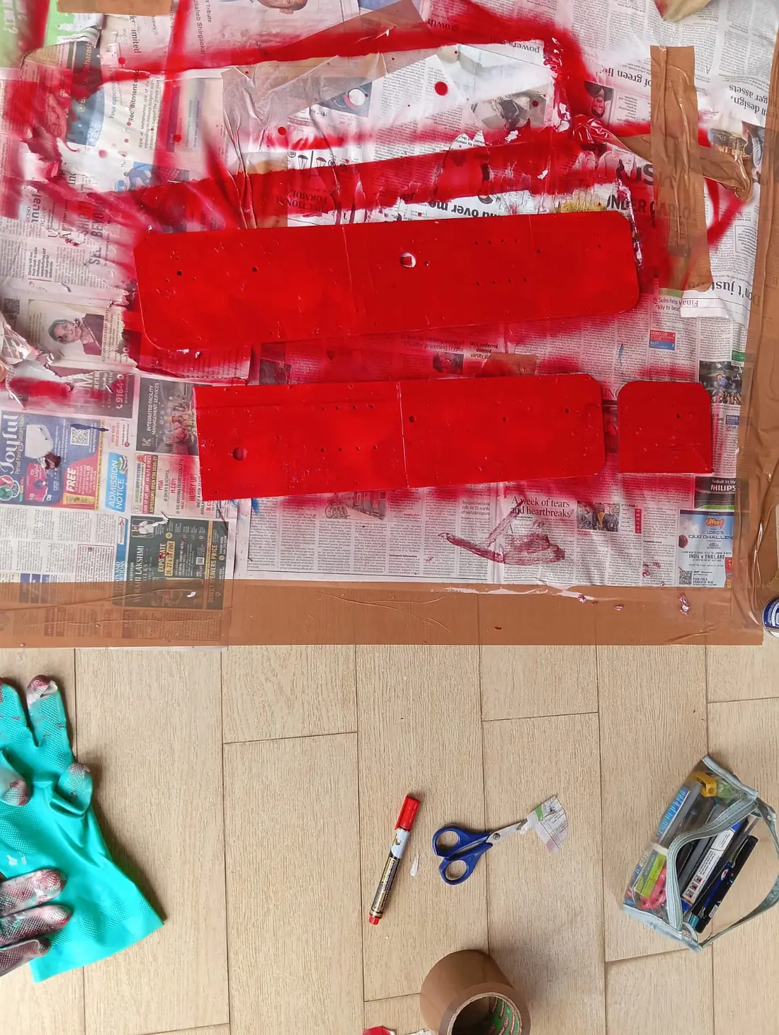
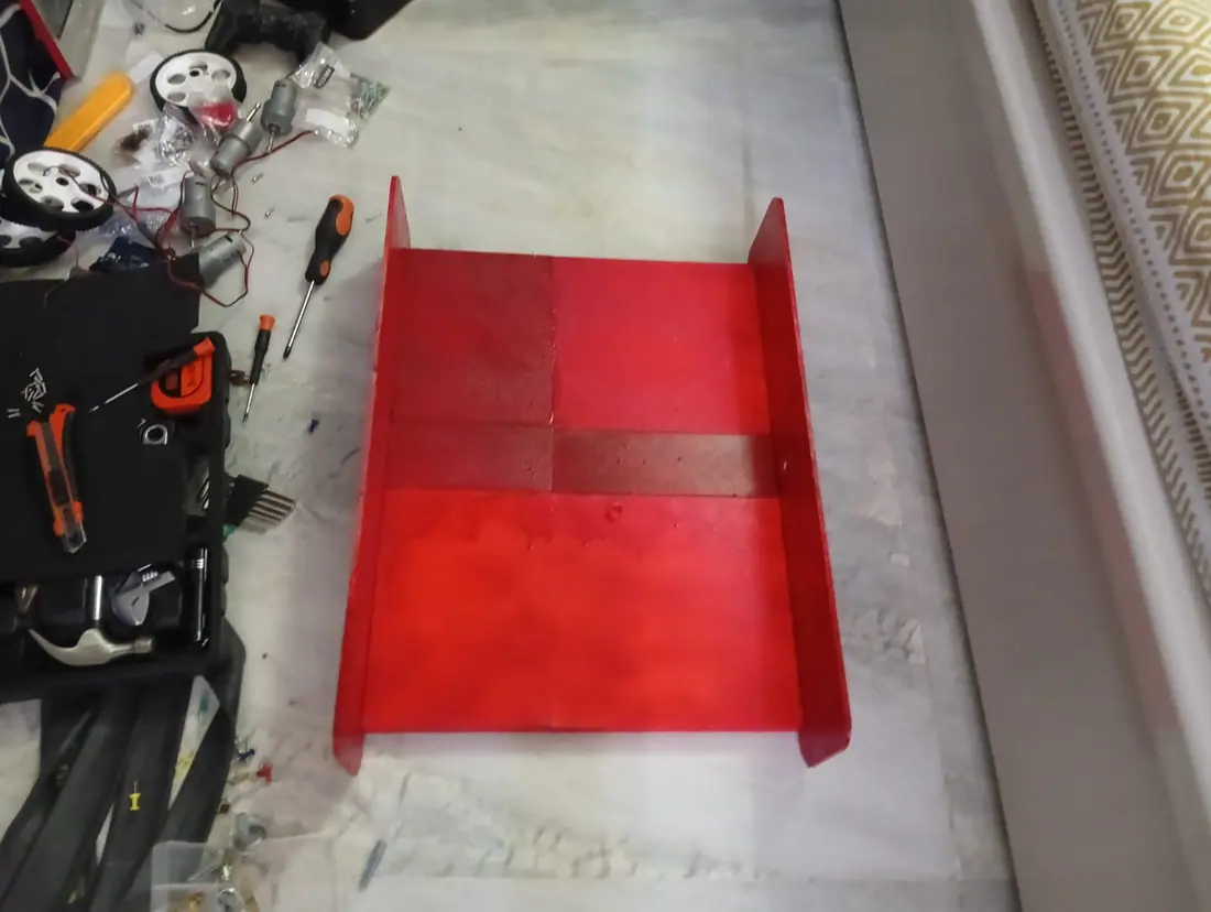
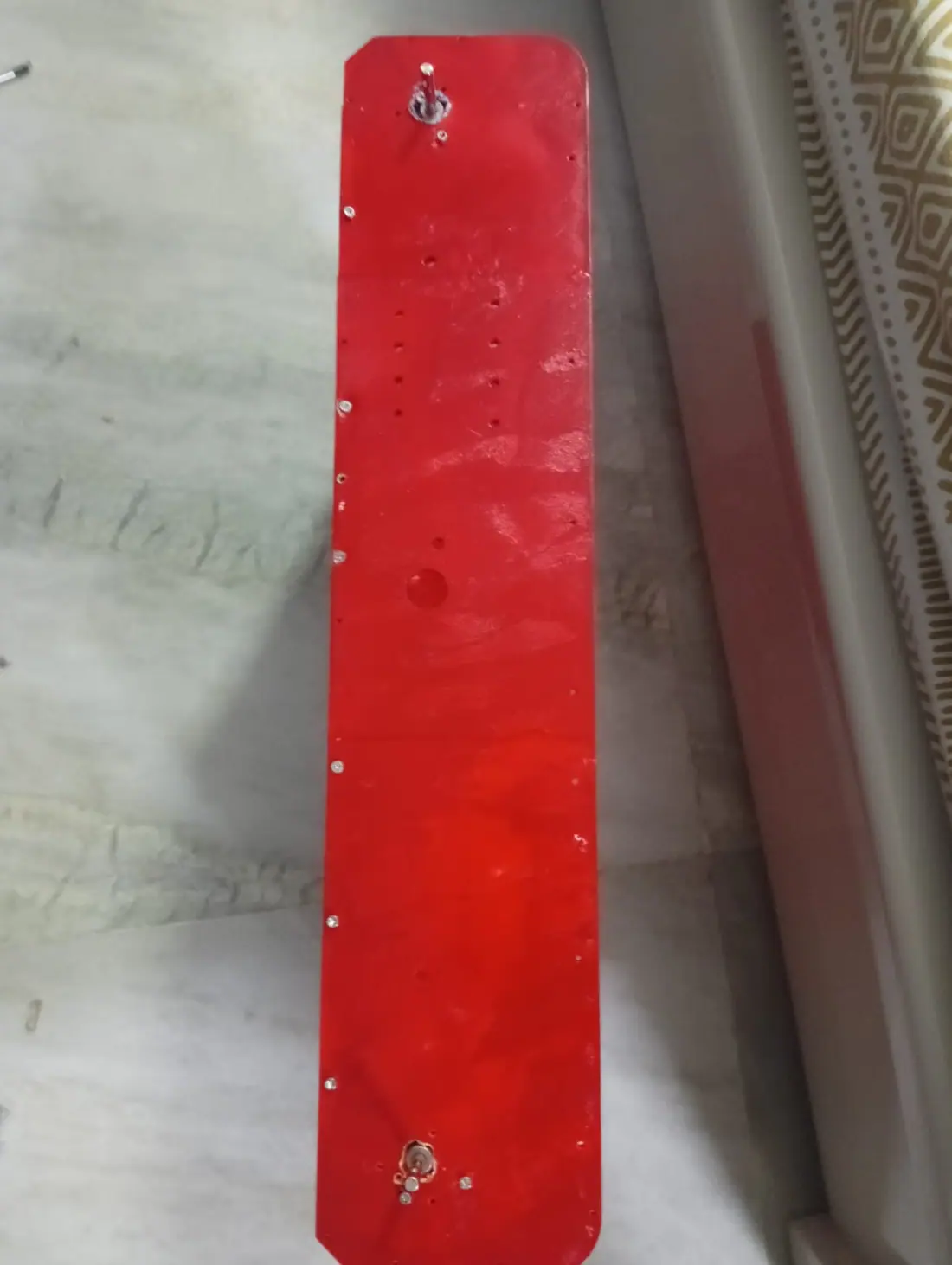
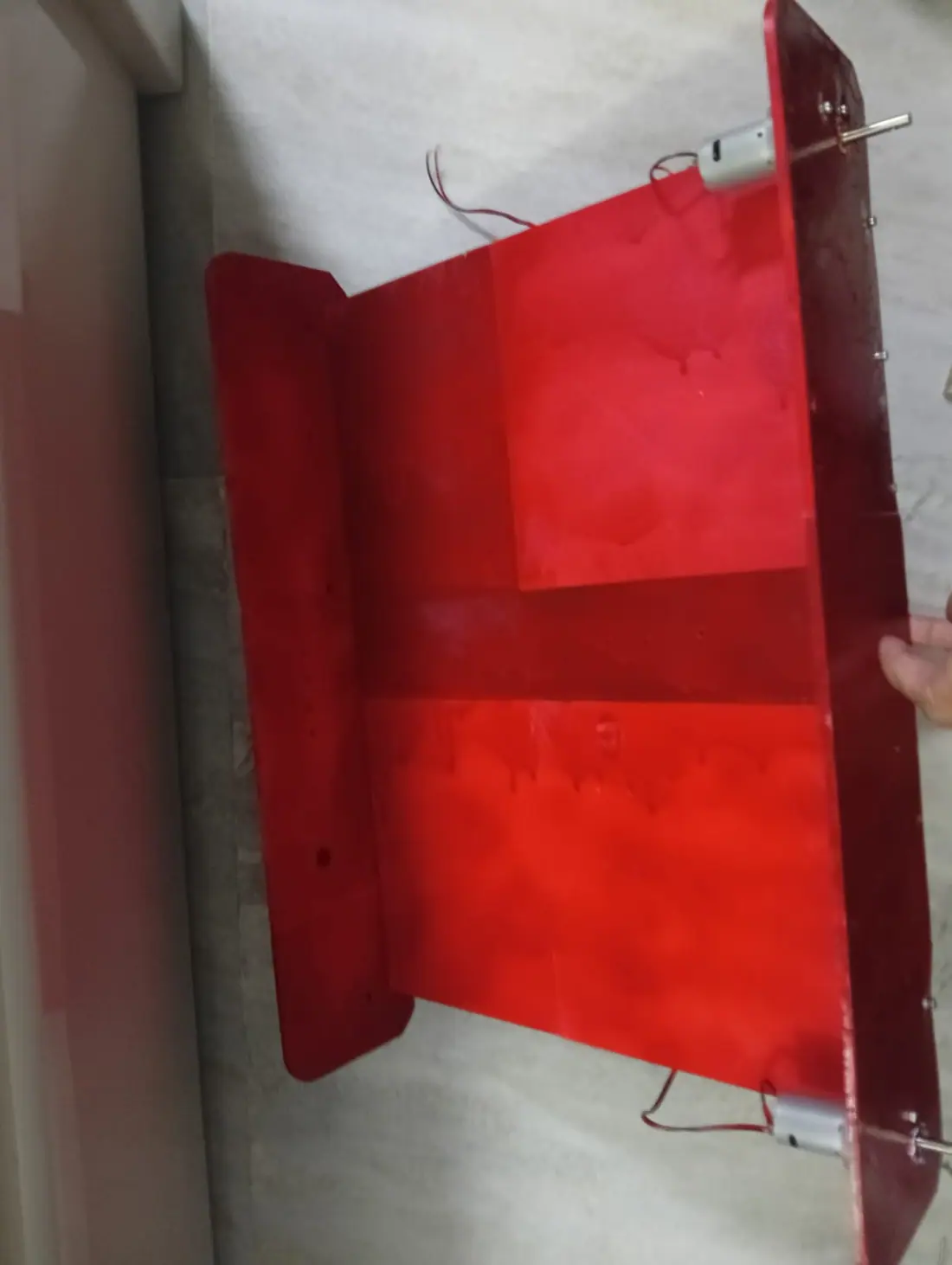
I painted the bottom of the chassis red, although it didn't look too great, maybe I need another coat of red ontop. I also painted the front and back panels which did come out pretty well. I started painting the side panels but I ran out of red paint so I temporarily spray painted those white instead.

Image 1 from devlog #41: Painting some more (30mins)Image 2 from devlog #41: Painting some more (30mins)Image 3 from devlog #41: Painting some more (30mins)
#42Painting sides and detailing (40mins)Aug 15, 2026

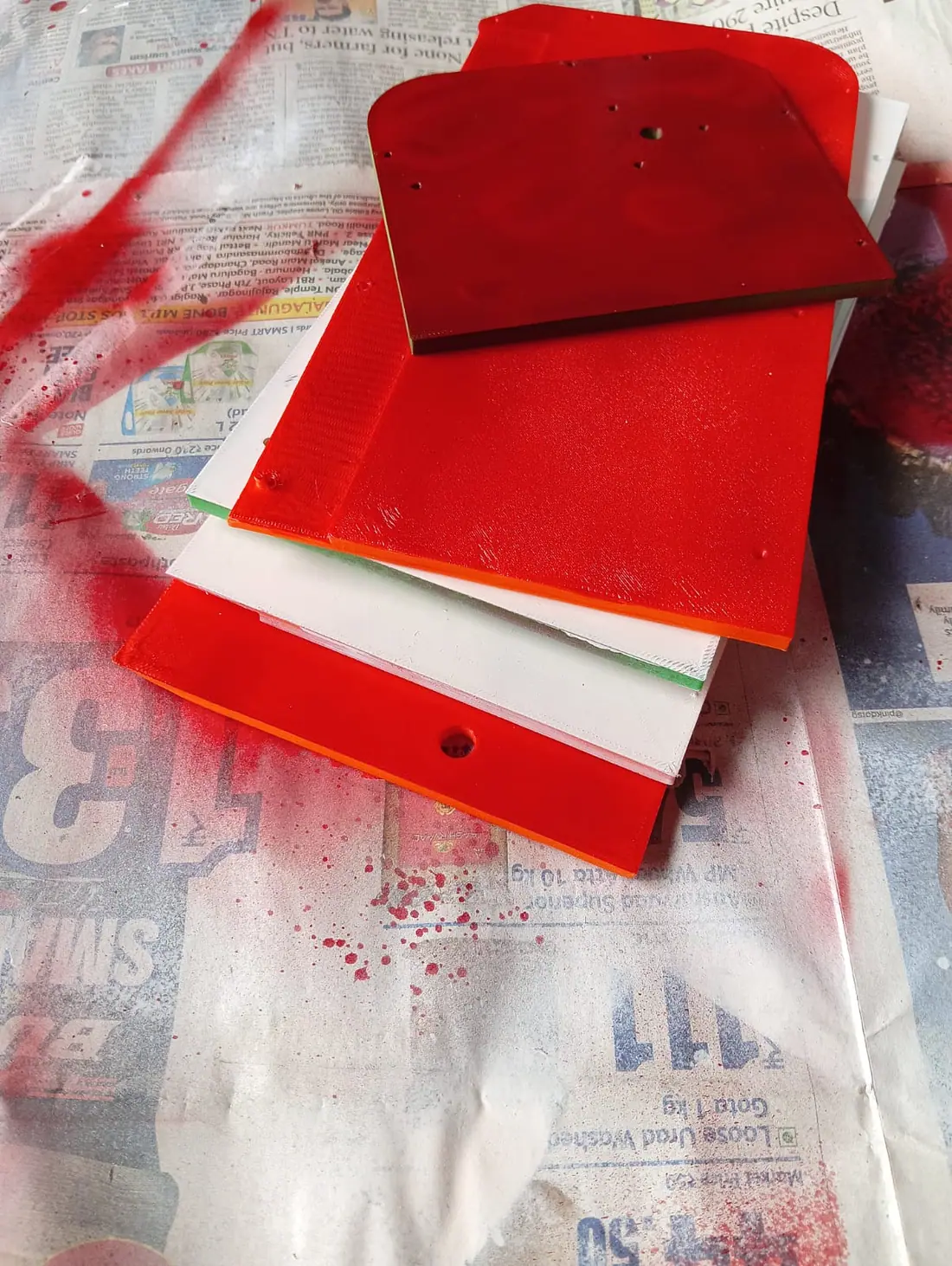
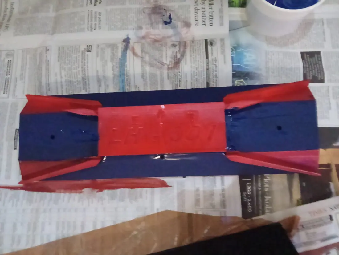
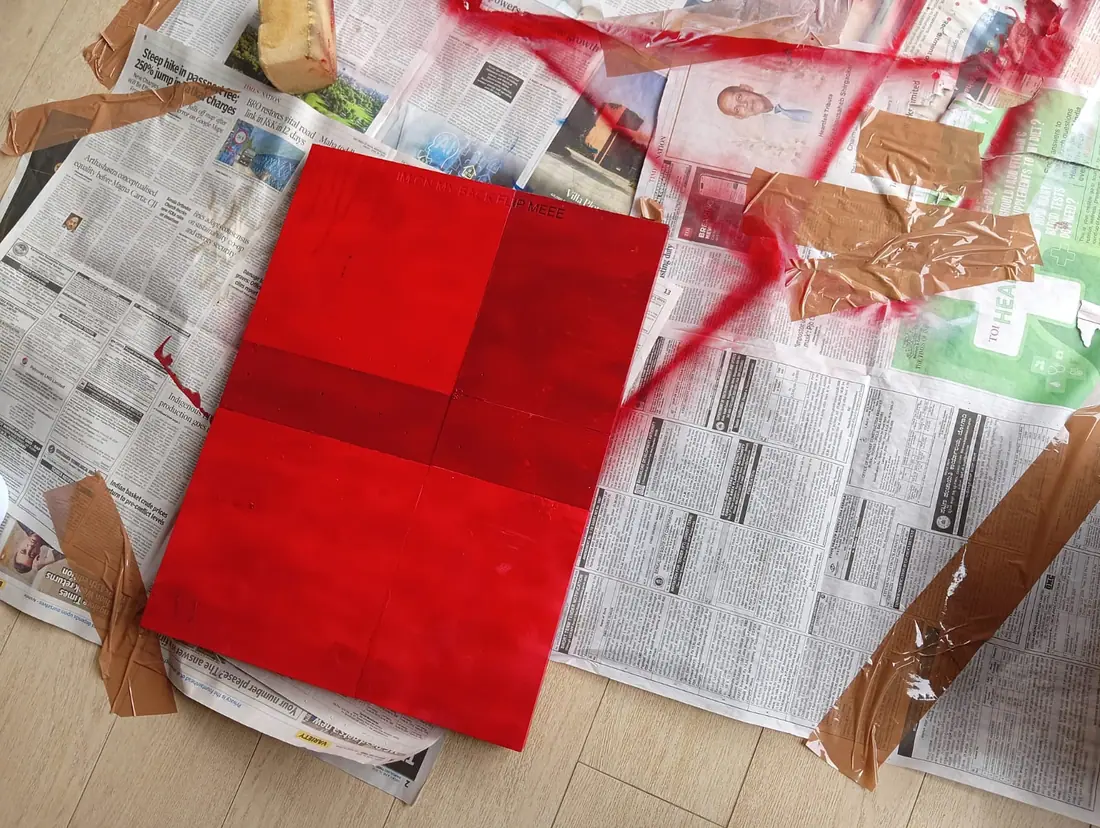
I painted the side panels red, after putting a coat of white primer on since I realised the red didn't look too great since every panel of a different colour had a different red appearance, and the white primer made it all come together so well, but obviously I have to wait for the red paint to dry for so long. I only have the other side of the sidepanels left and I'm done with the painting most probably.

Image 1 from devlog #42: Painting sides and detailing (40mins)Image 2 from devlog #42: Painting sides and detailing (40mins)Image 3 from devlog #42: Painting sides and detailing (40mins)Image 4 from devlog #42: Painting sides and detailing (40mins)
#43Painting Sidepanel and paint corrections (45mins)Aug 15, 2026

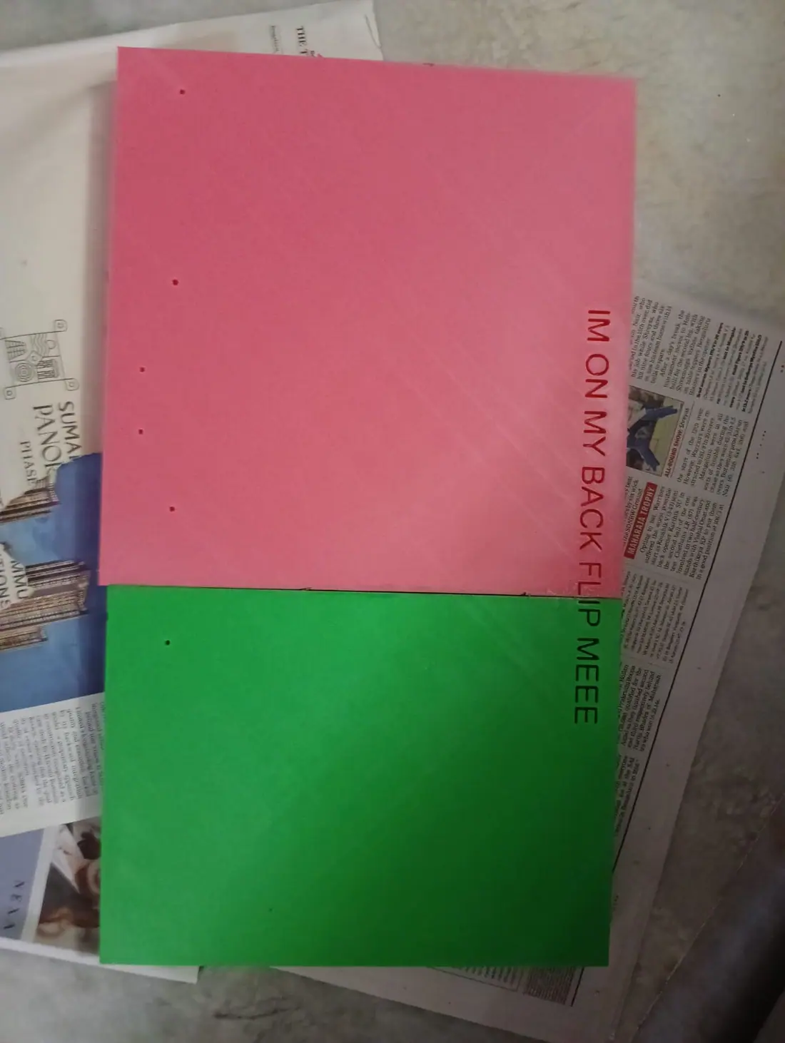
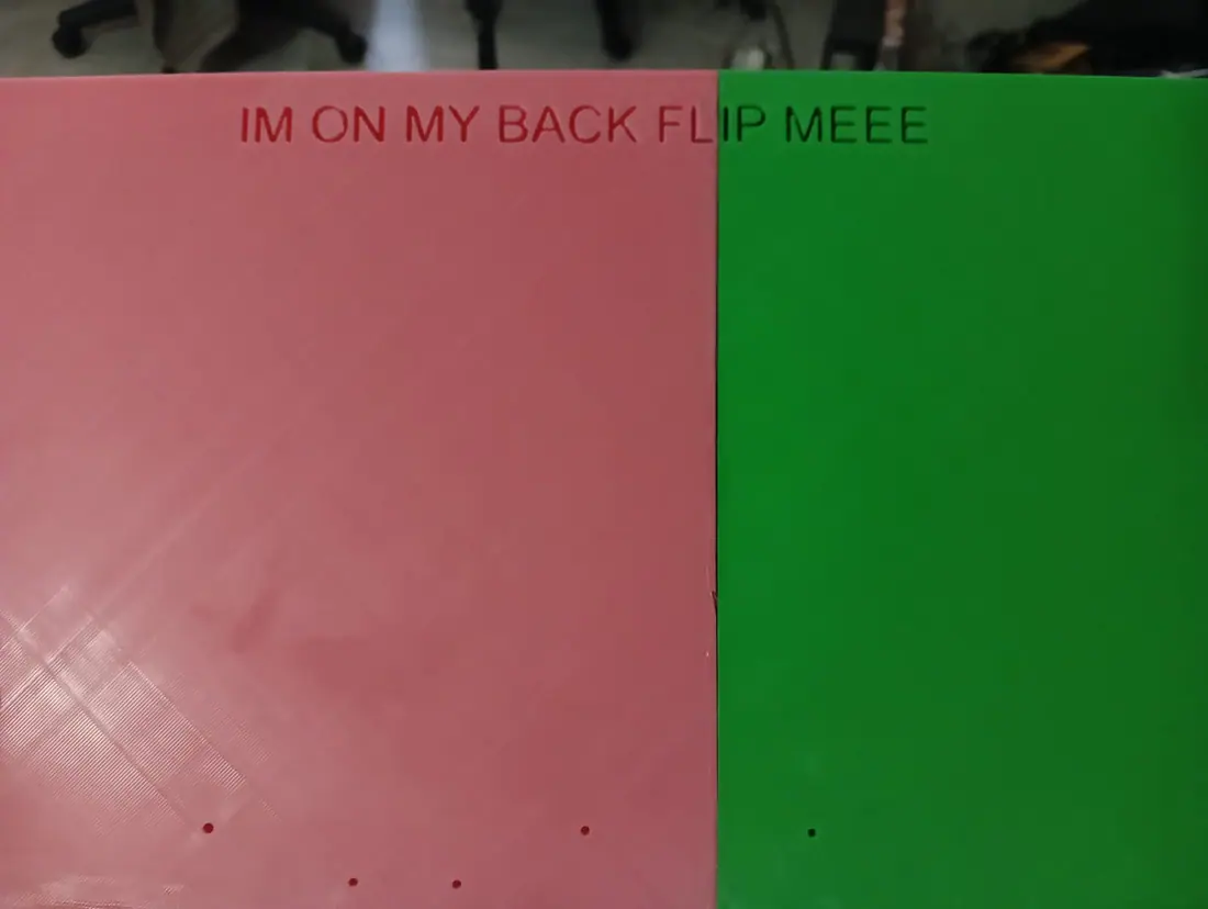
I flipped over the side panels and started painting the other side, but unfortunately the newspaper under the panel got stuck all over it so I had to spend a long time scraping it off, and since I couldn't get it all off I painted over it and then peeled again then painted again. The paint on the sides really didn't come out well but I guess it's better than the mess of colours there was initially. I also painted the sides of the bottom chassis panel and corrected some paint on that.

Image 1 from devlog #43: Painting Sidepanel and paint corrections (45mins)Image 2 from devlog #43: Painting Sidepanel and paint corrections (45mins)Image 3 from devlog #43: Painting Sidepanel and paint corrections (45mins)
#44★Assembly started (1h20mins)Aug 15, 2026

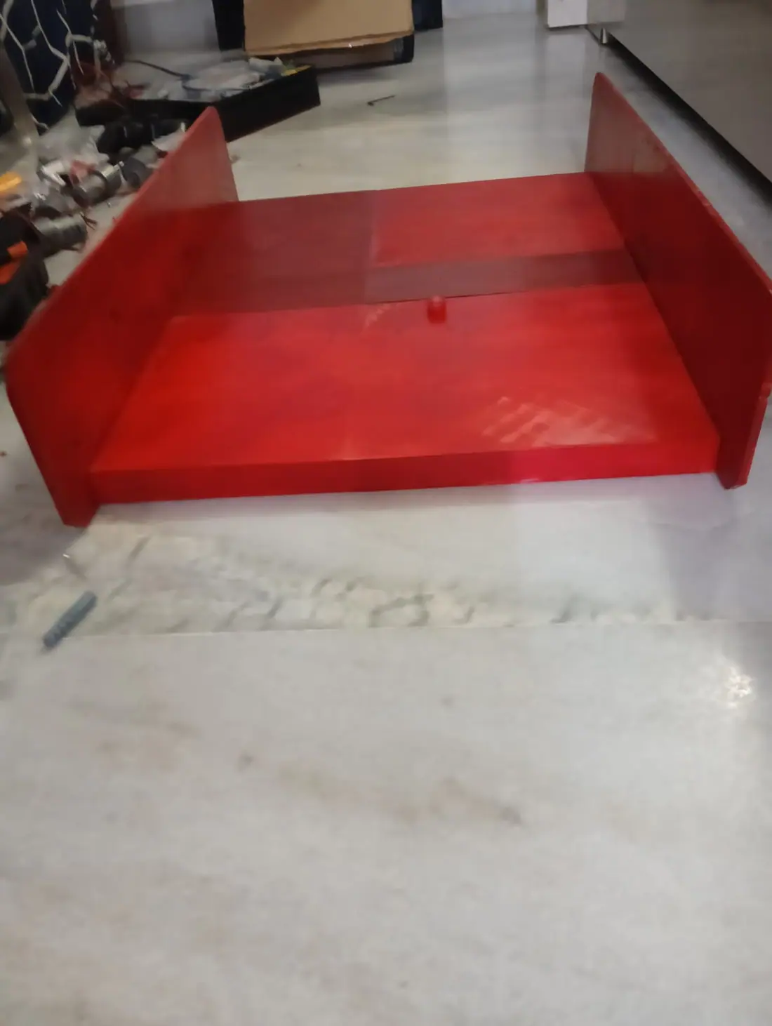
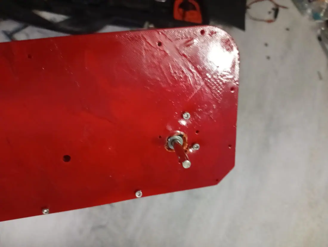
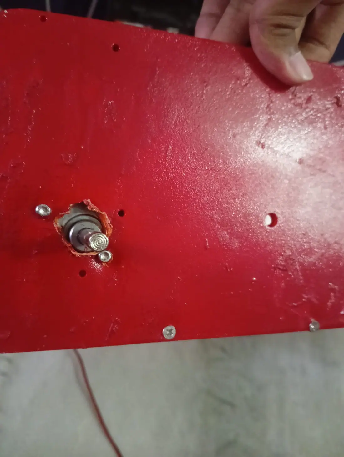
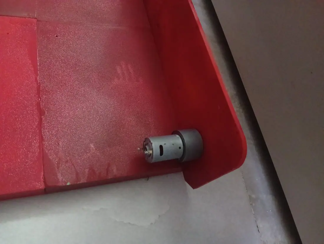
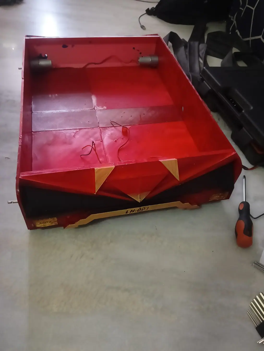
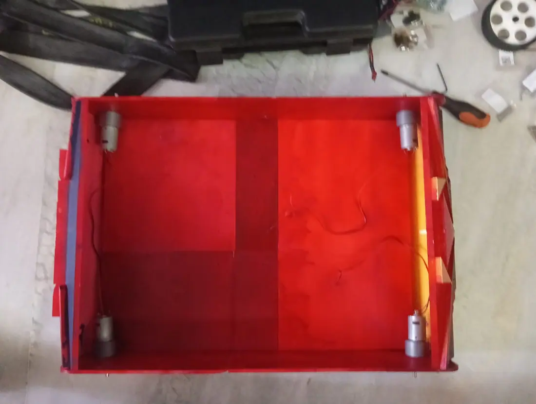
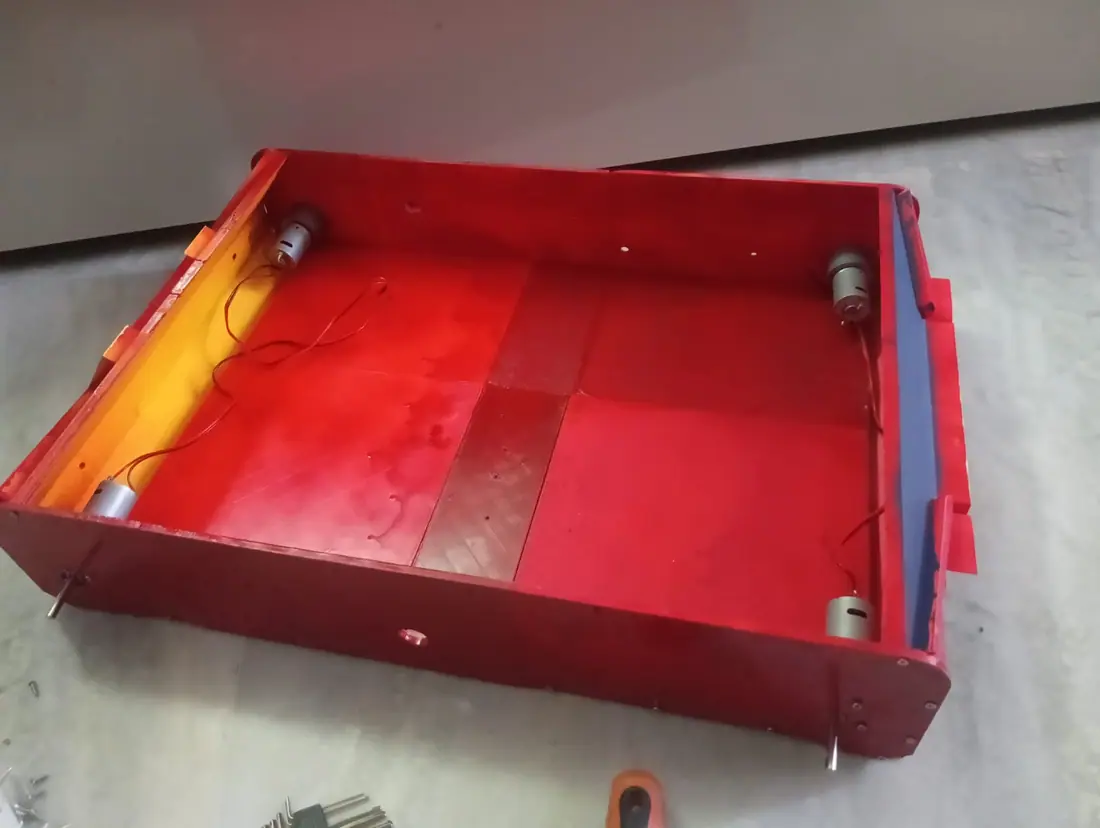
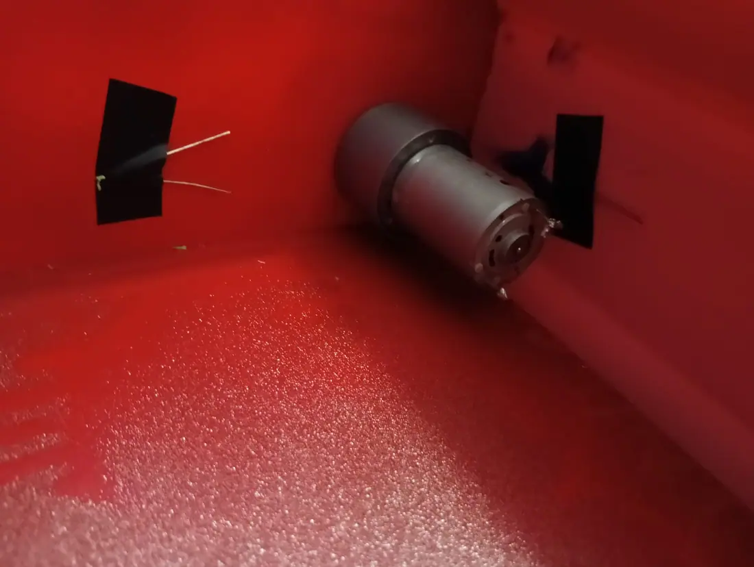
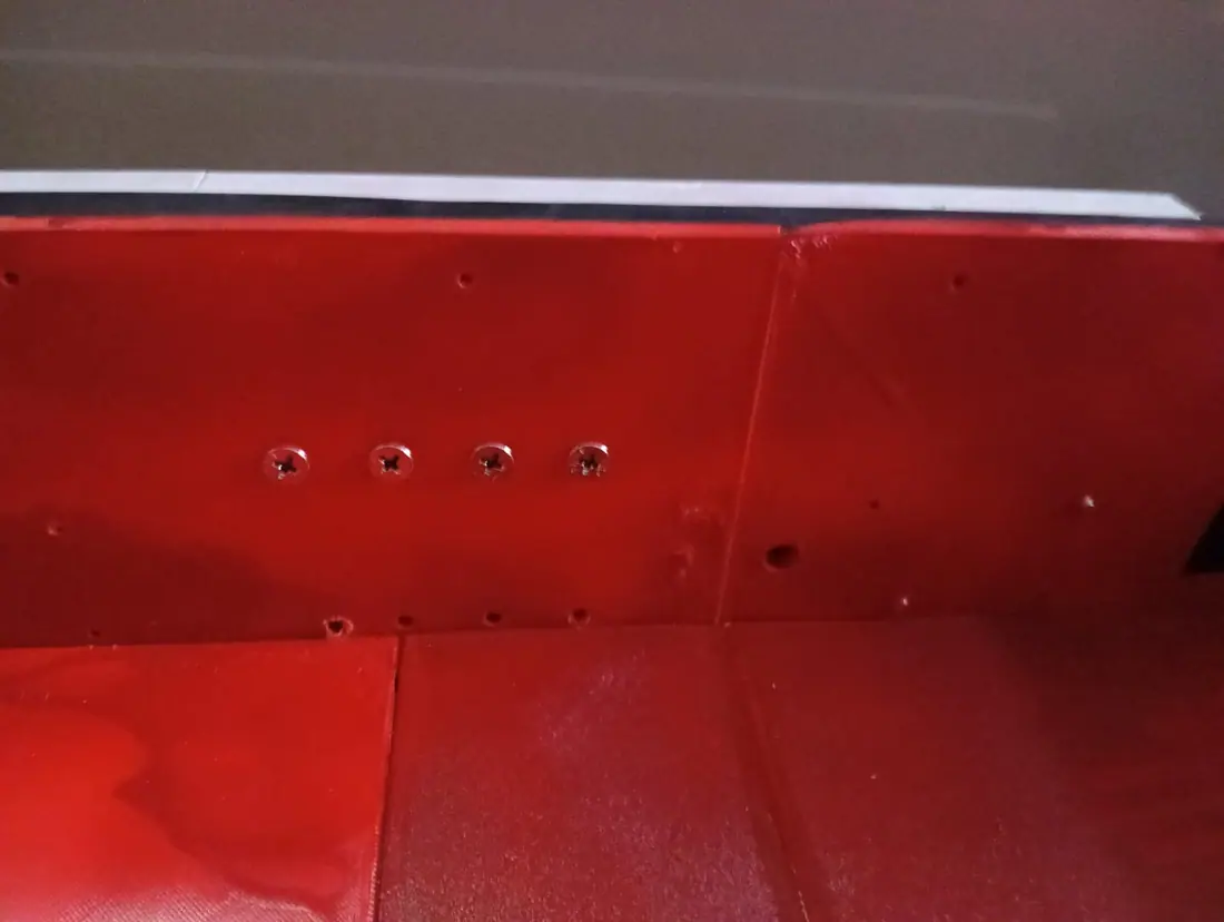
I started screwing the parts together. I had to refer to the CAD models to align the parts, and as it turns out the side panels and bottom panels didn't have the proper holes which is why in the readme I recommended using a drill and making the holes instead. Since I don't have a drill I used self tapping screws to make the holes (I used them for the holes that were aligned properly as well so that I could get the proper threading and size). I also now realise that none of the screws I ordered are magnetic which is making all of this a bit more annoying. Aligning the first screw hole of a panel is also really pissing off. I'm going to add a warning to the readme about how with low infill an improper hole could cause cracks, and that using a drill/self tapping screw people should be careful of the friction since it actually generates quite a lot of heat. I also realised that the motor shaft fits perfectly into the hole I made for it but what I didn't take into account was the motor has an intermediate size ring between the shaft and the body, so if I screw it in the motor won't be flat against the body, which is something I have to fix. Also a printing mistake meant that parts of the side panel had a bit of a gap from the bottom panel, so I took longer screws from an old project's spare parts and used those slightly bending the chassis.

Image 1 from devlog #44: Assembly started (1h20mins)Image 2 from devlog #44: Assembly started (1h20mins)Image 3 from devlog #44: Assembly started (1h20mins)Image 4 from devlog #44: Assembly started (1h20mins)
#45An Attempt At Motor MountingAug 15, 2026

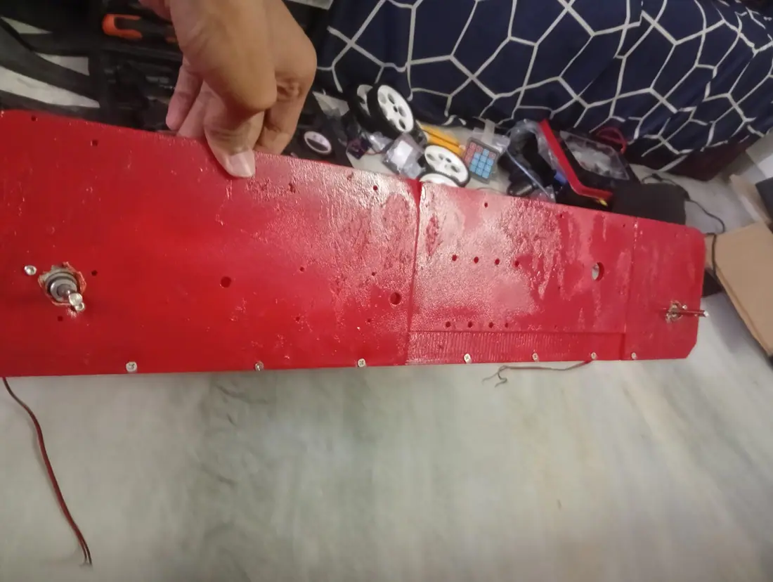
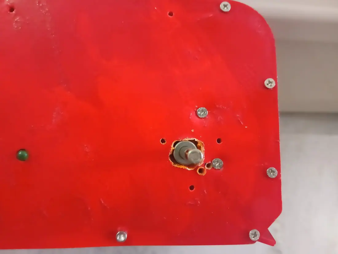
Since the sizing of the hole was wrong and I don't have a drill, I used the fact that plastic has a low melting point and a soldering rod to widen the hole to the right size for one panel. Unfortunately the screw holes are also misaligned now cause of that so I made the hole for one screw for the motor, but I misplaced the second hole since it's hard to get it exactly right, so I'll start using a marker and scale and try to be more precise with the other holes. I initially thought one screw would be enough but the other side of the motor is lifting so I need 2 or ideally 3.

Image 1 from devlog #45: An Attempt At Motor Mounting
#46Left Panel Motors Mounted (1.5 Hours)Aug 15, 2026

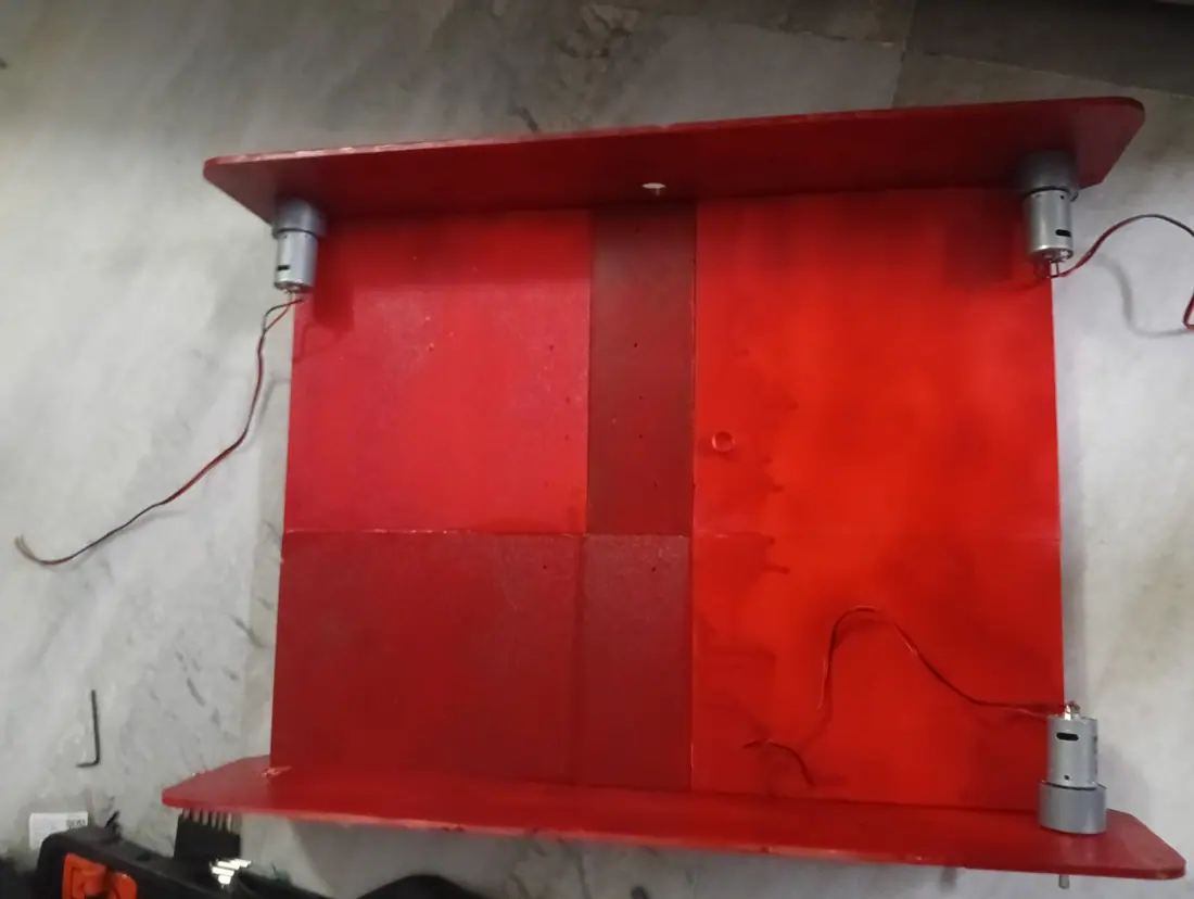
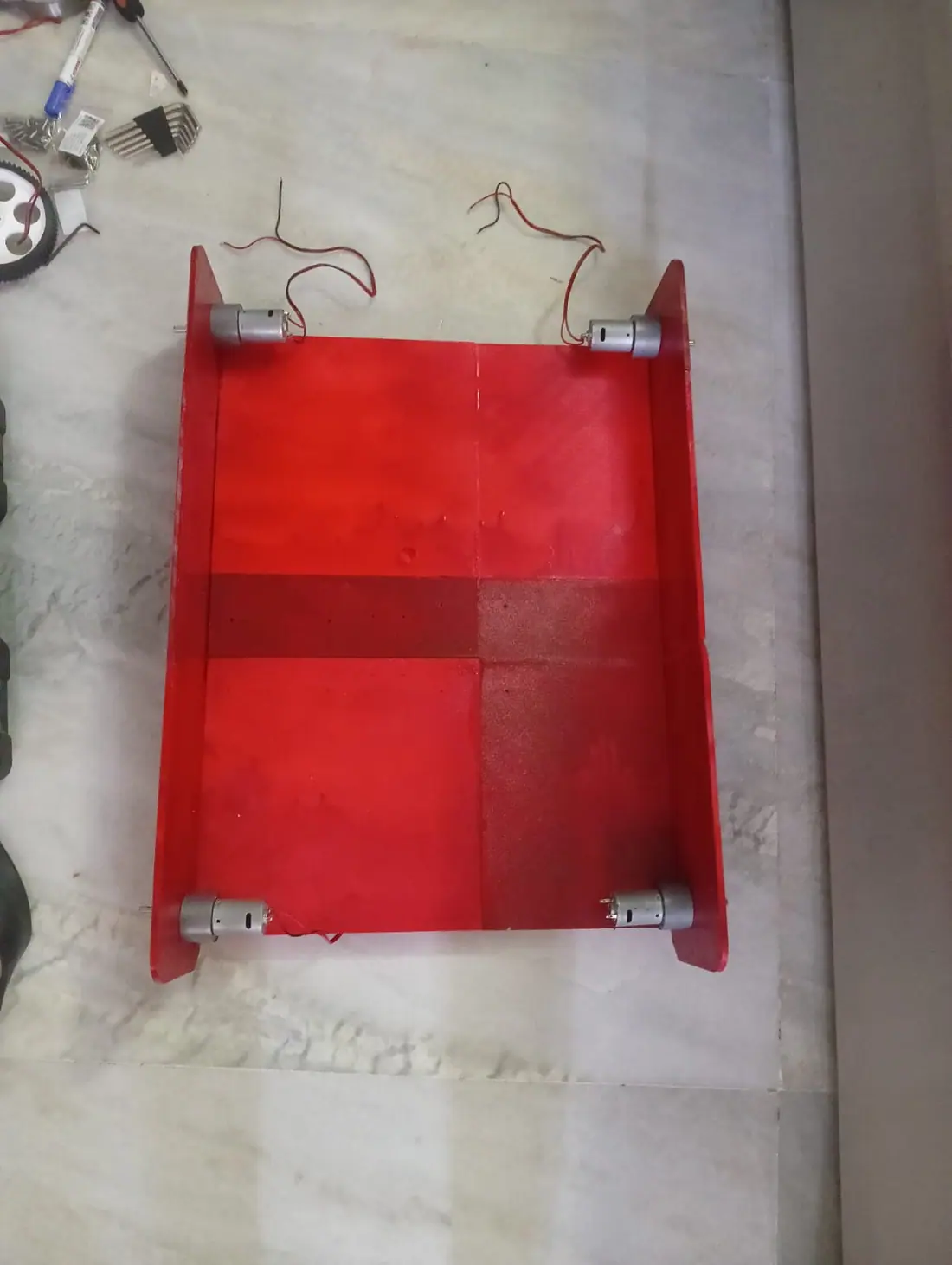
I painstakingly manually made the holes ( I may or may not have made a couple extra holes by accident as well), and attached the left panel's motors with 2 bolts each. I had to slowly make an indent first with a self tapping screw so that I could then screw that in completely, remove it, put a larger screw in, remove it, put the new bolt in and if it didn't fit properly put a screw through and remove it again and after all that hope that I aligned the hole correctly which most of the time I didn't. But After a lot of work I have managed one panel's motors. Since the motors aren't perfectly aligned, I'm very concerned about how that may mess with the track.

Image 1 from devlog #46: Left Panel Motors Mounted (1.5 Hours)Image 2 from devlog #46: Left Panel Motors Mounted (1.5 Hours)Image 3 from devlog #46: Left Panel Motors Mounted (1.5 Hours)Image 4 from devlog #46: Left Panel Motors Mounted (1.5 Hours)
#47Another Motor Bites The Dust (1.5 hours)Aug 15, 2026

I first made the hole with the soldering iron to fit the motor shaft (mmmm plastic fumes).I attached 1 more motor, which took a frustratingly long time since the new screw holes would either not align right, or not slot right, or just do something really weird.Not to mention the incredible amount of time it took to actually make the holes with the self tapping screws without a drill. The motor mounting taking so long is the equivalent of a 5 minute job turning into a weekend job when a screw strips. If the original holes were right I would've been done so long ago with this. One thing I am happy about though is the paint seems to have stuck to the plastic really well, I keep missing with the screwdriver and hitting the chassis but the paint is barely damaged, I was scared that the paint would be peeling off even without that so that's a plus point. There's just one more motor and I can move ahead. I was hoping to be wayy further along and not spend genuine hours on the motor mounting which should've been a quick job.

Image 1 from devlog #47: Another Motor Bites The Dust (1.5 hours)Image 2 from devlog #47: Another Motor Bites The Dust (1.5 hours)Image 3 from devlog #47: Another Motor Bites The Dust (1.5 hours)Image 4 from devlog #47: Another Motor Bites The Dust (1.5 hours)
#48Final Motor Mounted (50Mins)Aug 15, 2026

I finally finished mounting all the motors, this final motor went a lot quicker since I had already made the wider hole for the shaft yesterday, and I got lucky and made only the exact hole I needed (though I had to put the screw in a bit cockeyed to make it work). Now I can finally move onto adding the rest of the parts.

Image 1 from devlog #48: Final Motor Mounted (50Mins)Image 2 from devlog #48: Final Motor Mounted (50Mins)Image 3 from devlog #48: Final Motor Mounted (50Mins)Image 4 from devlog #48: Final Motor Mounted (50Mins)
#49Attaching Front and Back Panels (53Mins)Aug 15, 2026

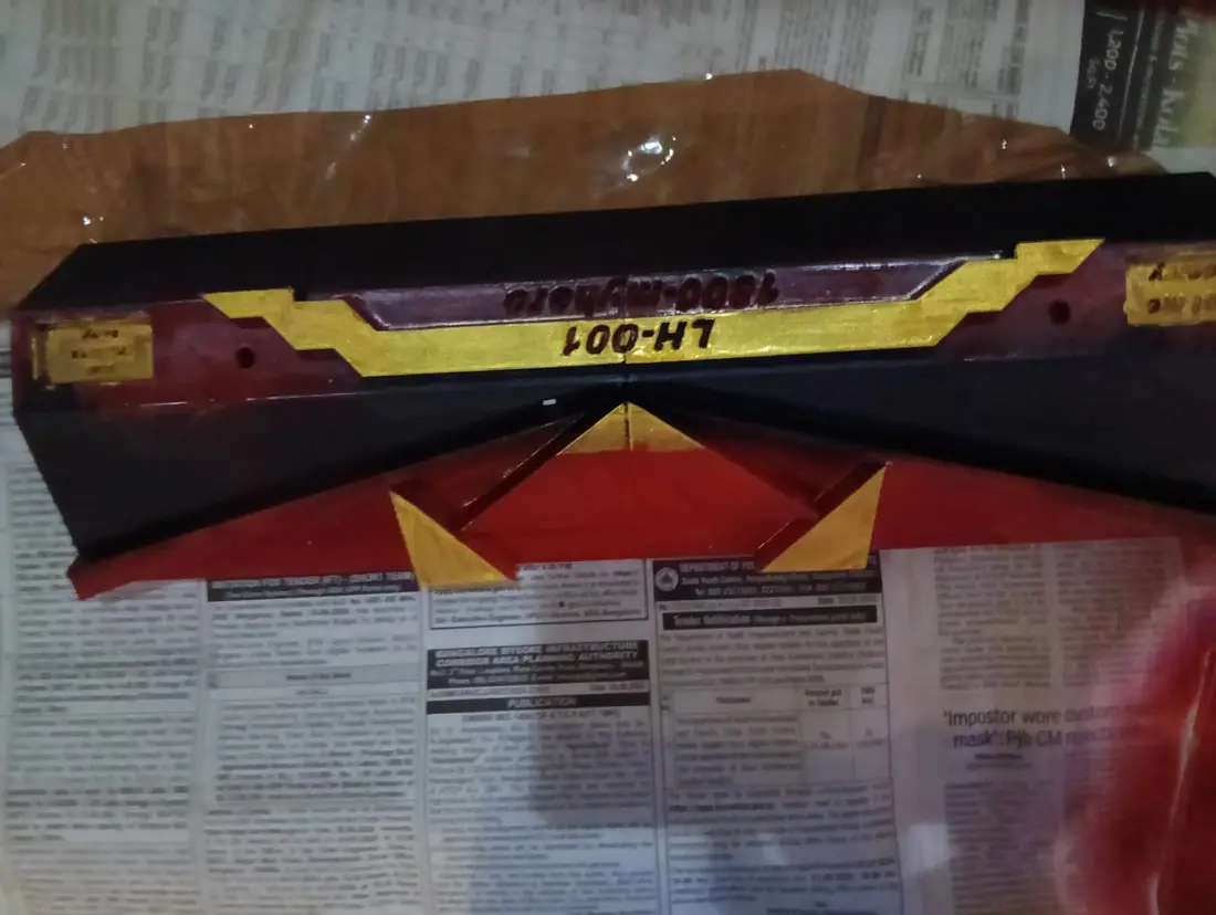
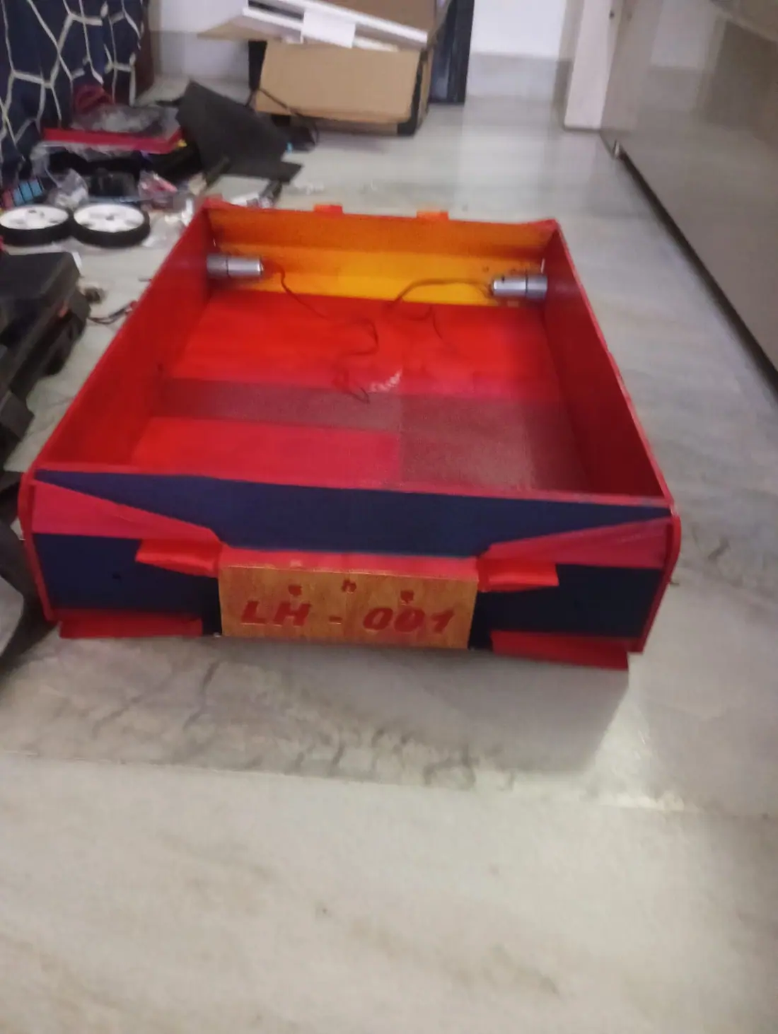
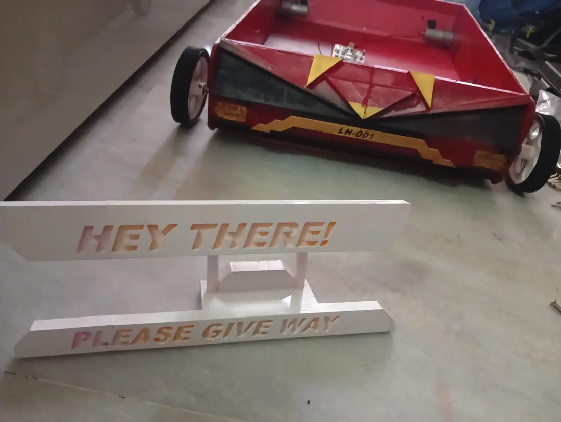
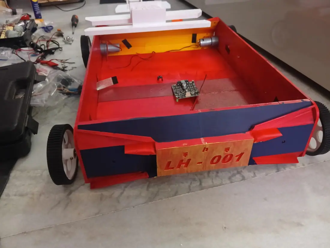
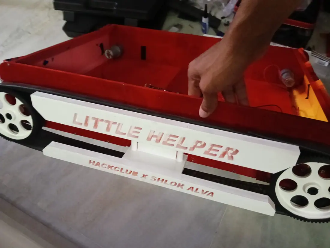
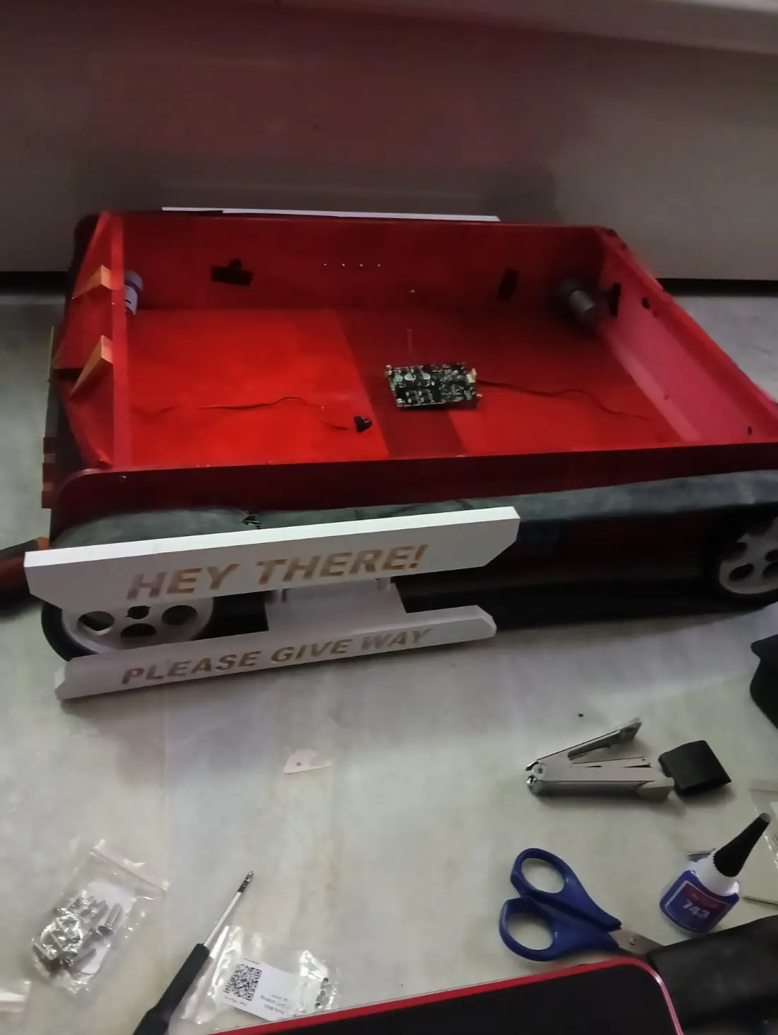
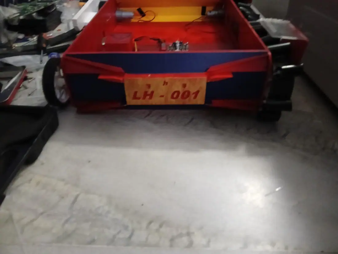
I attached the front panel to the main chassis, first using the self tapping screws to make the threading and then adding the actual screws. I also added a little bit more gold to the liscence plate to make it look more uniform. Maybe I should've added the LEDs to the panels before attaching them like I said in my Readme but do as I say and not as I do I guess. As it turns out I also put the sidepanels on the wrong sides, so the back and front are reversed and the back panel doesn't align properly with the screw holes. The top 2 screws for the back panel aligned perfectly, so after screwing those 2 in I thought I would make new holes for the rest, then I realised that the back panel is rigid enough to not move but is free enough to act as a slideable /openable part so that is now a feature and not a bug.

Image 1 from devlog #49: Attaching Front and Back Panels (53Mins)Image 2 from devlog #49: Attaching Front and Back Panels (53Mins)Image 3 from devlog #49: Attaching Front and Back Panels (53Mins)Image 4 from devlog #49: Attaching Front and Back Panels (53Mins)
#50NumPad, Buzzer, LED mounting (78mins)Aug 15, 2026

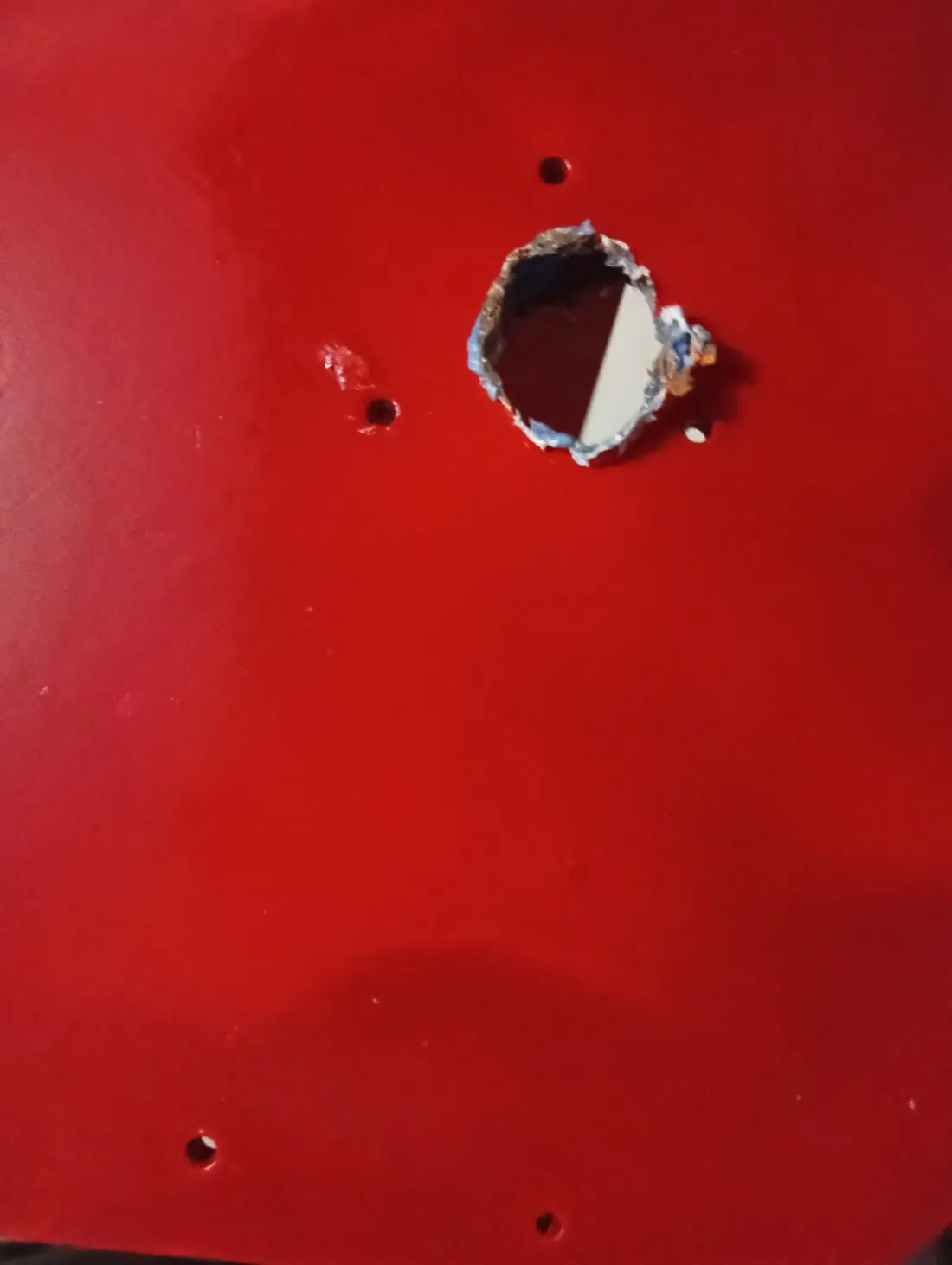
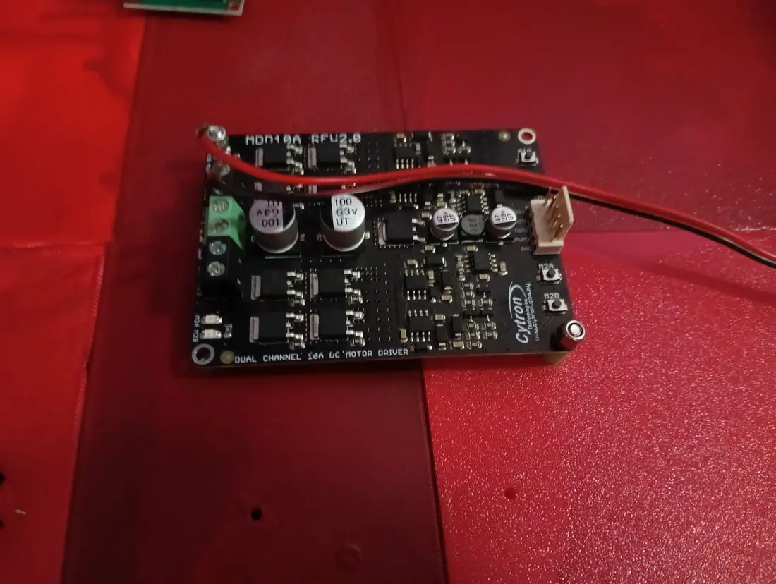
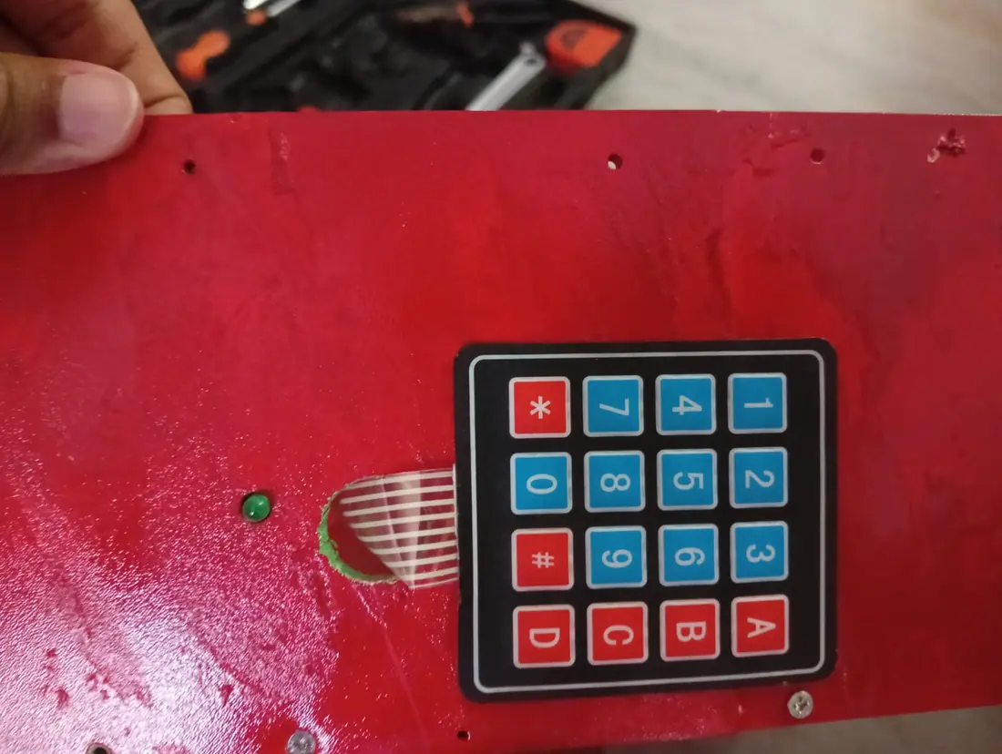
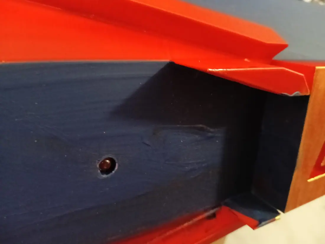
I put the leds into the holes and stuck them in using tape from the inside, I had to keep cross referencing the CAD design since I was really confused that nothing was matching up correctly. As it turns out I stuck the side panels together in the wrong order, so I'm going to have to improvise. After I stuck the LEDS I made the holes for the motor drivers wide enough and bolted the motor driver with 2 screws and spacers. I also stuck the numpad on the side and brought the cable inside, I had to widen the hole a bit so that the cable would squeeze through and I'm not sure if I damaged the cable while pushing it through. I also had to mount the numpad sideways so that the wire wouldn't break. I put the buzzer into the little slot I made for it and stuck it in there as well.

Image 1 from devlog #50: NumPad, Buzzer, LED mounting (78mins)Image 2 from devlog #50: NumPad, Buzzer, LED mounting (78mins)Image 3 from devlog #50: NumPad, Buzzer, LED mounting (78mins)Image 4 from devlog #50: NumPad, Buzzer, LED mounting (78mins)
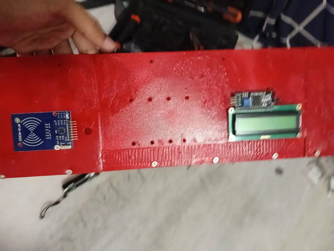
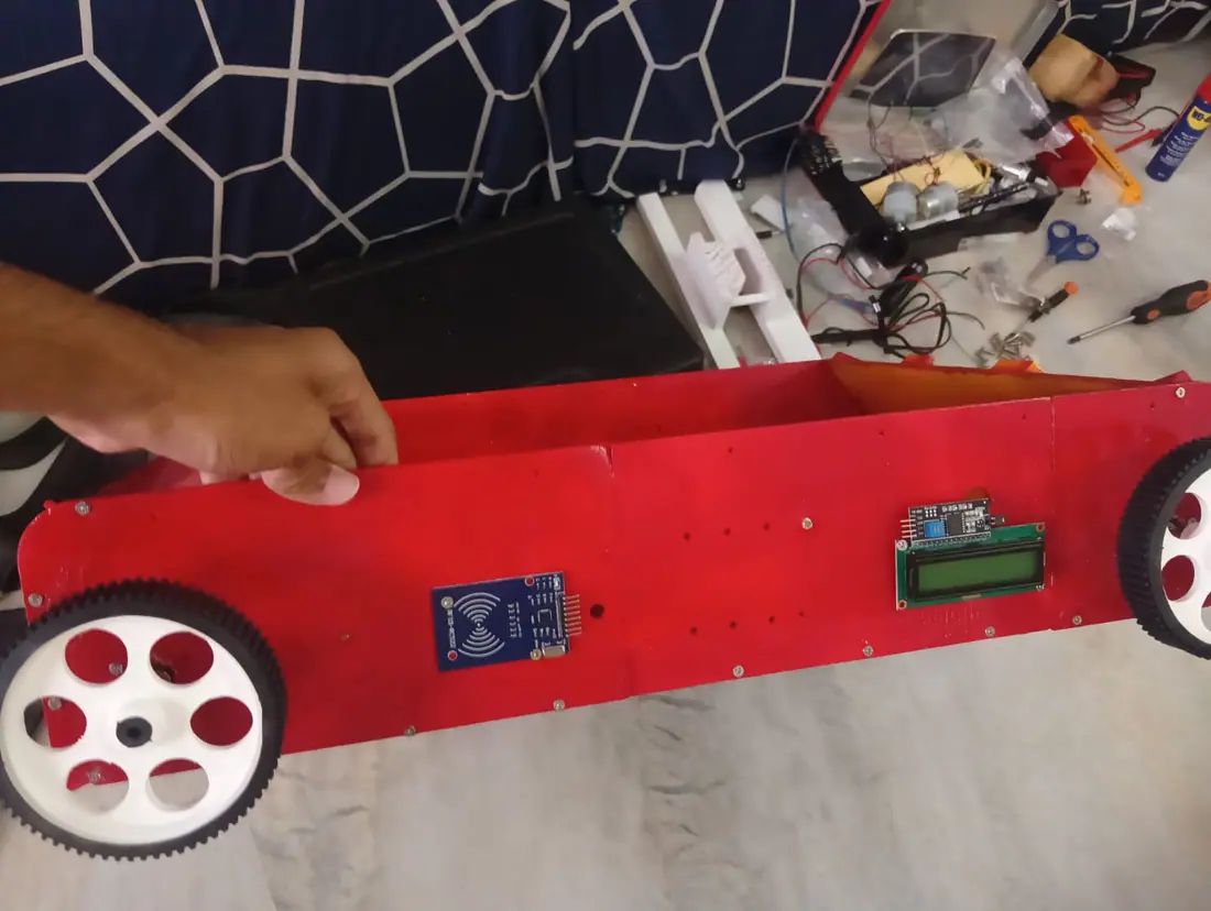
#51Mounting RFID and LCD and Attempting to Mount the WheelsAug 15, 2026

I made the holes for and mounted the LCD and RFID Scanner, after which I decided I would move on and mount the wheels onto the bot. The first wheel screwed on but didn't move properly with the motor when I tried to rotate it by hand, so I assumed that the wheel wasn't mounting properly, but then I put the screw directly into the motor to try and turn it and the motor wouldn't turn. So I then Jerry Rigged a battery to test all 4 motors directly, and both the motors on the left panel are jammed for some reason, so now I have to undo my hardwork and remove the left motors and figure out what's wrong with them.

Image 1 from devlog #51: Mounting RFID and LCD and Attempting to Mount the WheelsImage 2 from devlog #51: Mounting RFID and LCD and Attempting to Mount the Wheels
#52Motor Troubleshooting (44mins)Aug 15, 2026

Since the motors weren't working yesterday, I took one motor off and opened it and sprayed some wd40 inside. Since it was working fine now I reattached it to the chassis and tested it again, but oddly it didn't work anymore. So I took it off again and tried to run the motor with the screws inside the mounting holes and sure enough that's when it jammed. So one quick google search later I figured out that the screws were too deep in the motor, so I swapped the screws for shorter M3*10mm Phillip's Head screws. Then I switched the screws for the other broken motor and the other 2 functional motors to maintain uniformity since otherwise one side has to be removed with a screwdriver and the other with an allen key.

Image 1 from devlog #52: Motor Troubleshooting (44mins)
#53Mounted the Wheels (27mins)Aug 15, 2026

I mounted the wheels onto the motor shafts and they do look slightly off center, and I'm hoping that the tracks and guiderails account for that. I also tried to screw in the guiderails, but realised I'd have to widen the holes slightly like I did for everything else, which I shall do next time.

Image 1 from devlog #53: Mounted the Wheels (27mins)Image 2 from devlog #53: Mounted the Wheels (27mins)Image 3 from devlog #53: Mounted the Wheels (27mins)
#54GuideRails and Track Base (1h3min)Aug 15, 2026

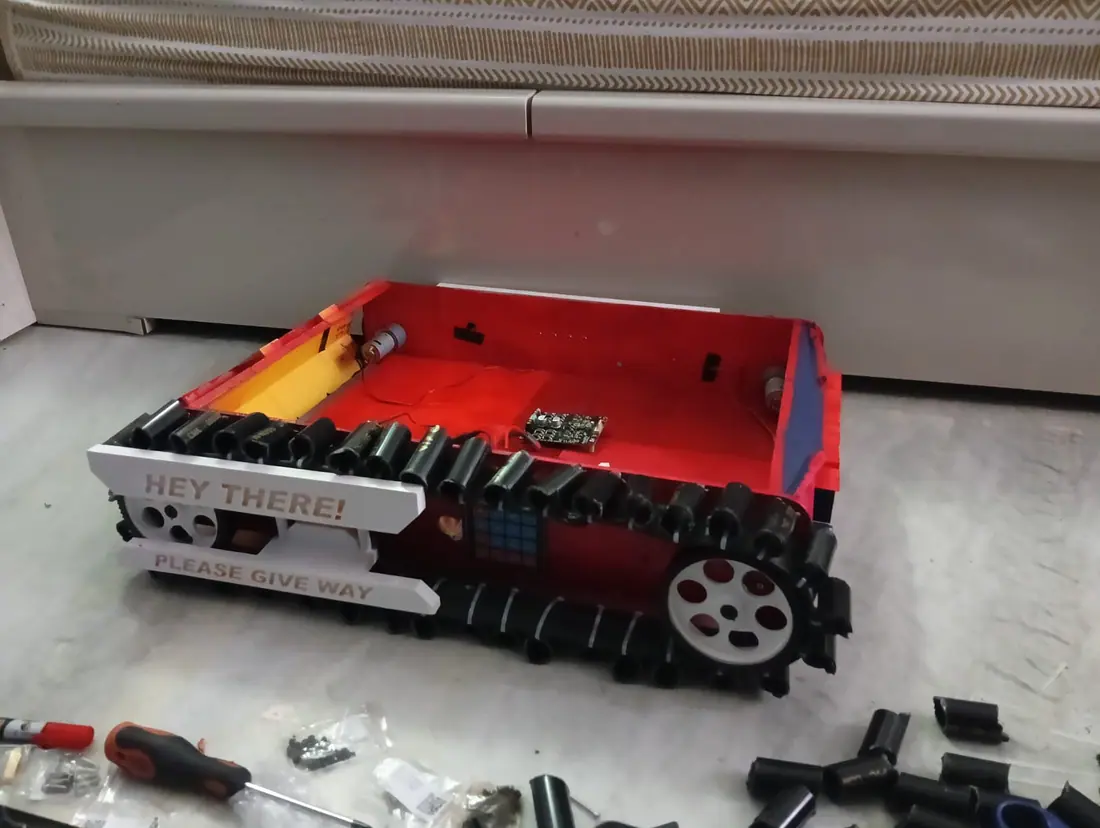
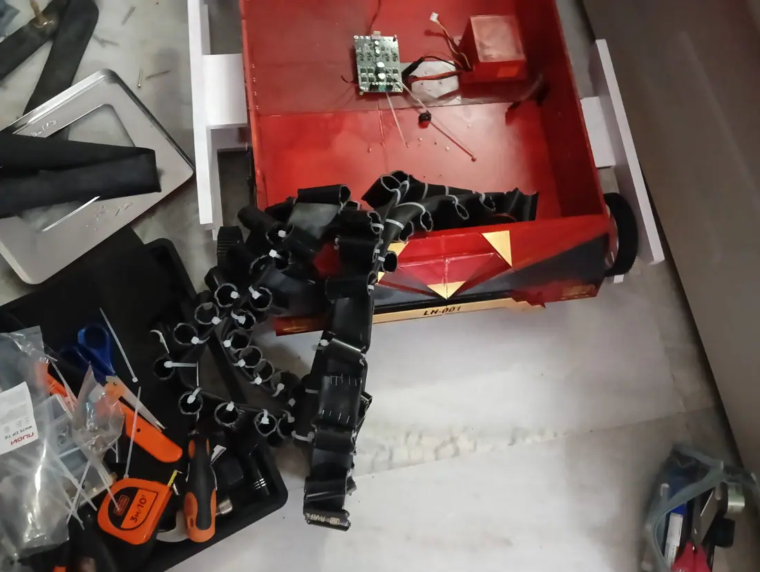
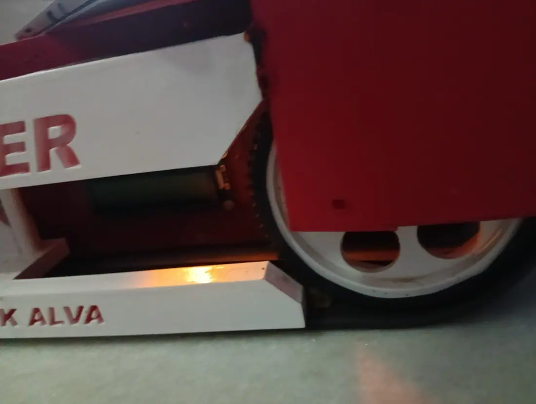
I widened the holes for the guiderails by just screwing in a screw before actually securing it to the chassis. The Guiderails aren't exactly where they're supposed to be since some of the panels got mixed up, but I'm hoping that won't end up being an issue. I didn't secure the bottom screws since it was sturdy enough with just the top and the bottom screws weren't inserting properly. One of the guiderails had gotten damaged in shipping, so I used some tape to just make sure it remained intact. Then I took some inner bicycle tubes and cut them and placed them over the tires so that they have high tension. The tracks aren't held in place properly by the guiderails yet, but I'm hoping I can fix that with the pvc pipes that go ontop of the guiderails with zipties, which I measured should be 1.6cm long per segment.

Image 1 from devlog #54: GuideRails and Track Base (1h3min)Image 2 from devlog #54: GuideRails and Track Base (1h3min)Image 3 from devlog #54: GuideRails and Track Base (1h3min)Image 4 from devlog #54: GuideRails and Track Base (1h3min)
#55Sawing the Tubes for the Tracks (1H23mins)Aug 15, 2026

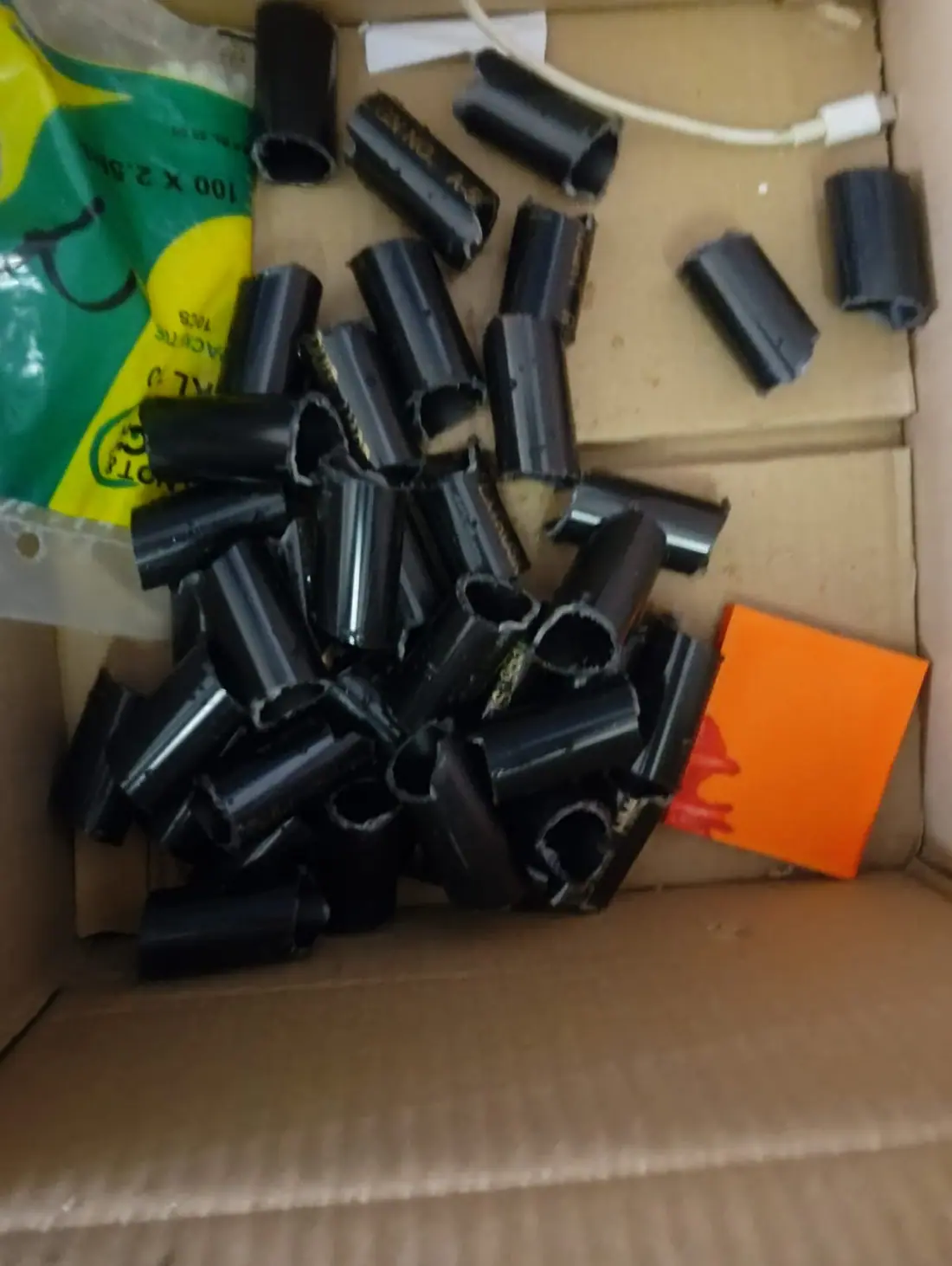
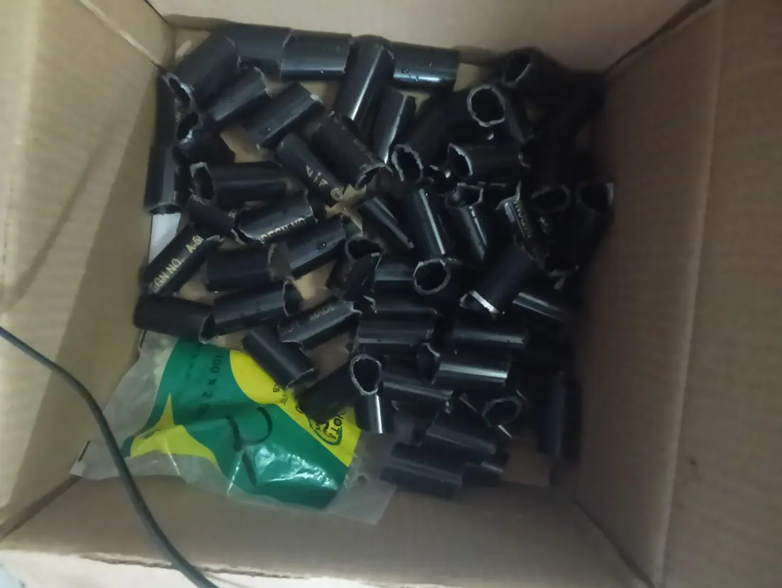
I worked on the tubes that'll attach to the bicycle inner tubing. I cut marked out spots to cut 1.6inches apart on am long electrical conduit pipe and then started sawing the pieces. I had to take a break at some points because my hands honestly started to hurt. I would love some power tools to do this, but it's probably for the best that I don't have them since I'd end up losing a finger.

Image 1 from devlog #55: Sawing the Tubes for the Tracks (1H23mins)
#56Mounting Battery Holder and Sawing(1H19Mins)Aug 15, 2026

I melted a small hole in the battery holder, since I printed the hole for the cables on the wrong side, then after that I fit the battery and lid in and it fit perfectly. So perfectly infact that I will have a lot of difficulty actually getting it open again. Then after mounting the battery holder to the chassis I finished sawing the rest of the electrical conduit pvc piping for the tracks. My hands ache, my back aches,so hopefully it works.

Image 1 from devlog #56: Mounting Battery Holder and Sawing(1H19Mins)Image 2 from devlog #56: Mounting Battery Holder and Sawing(1H19Mins)
#57Battery Holder Design and Right TrackAug 15, 2026

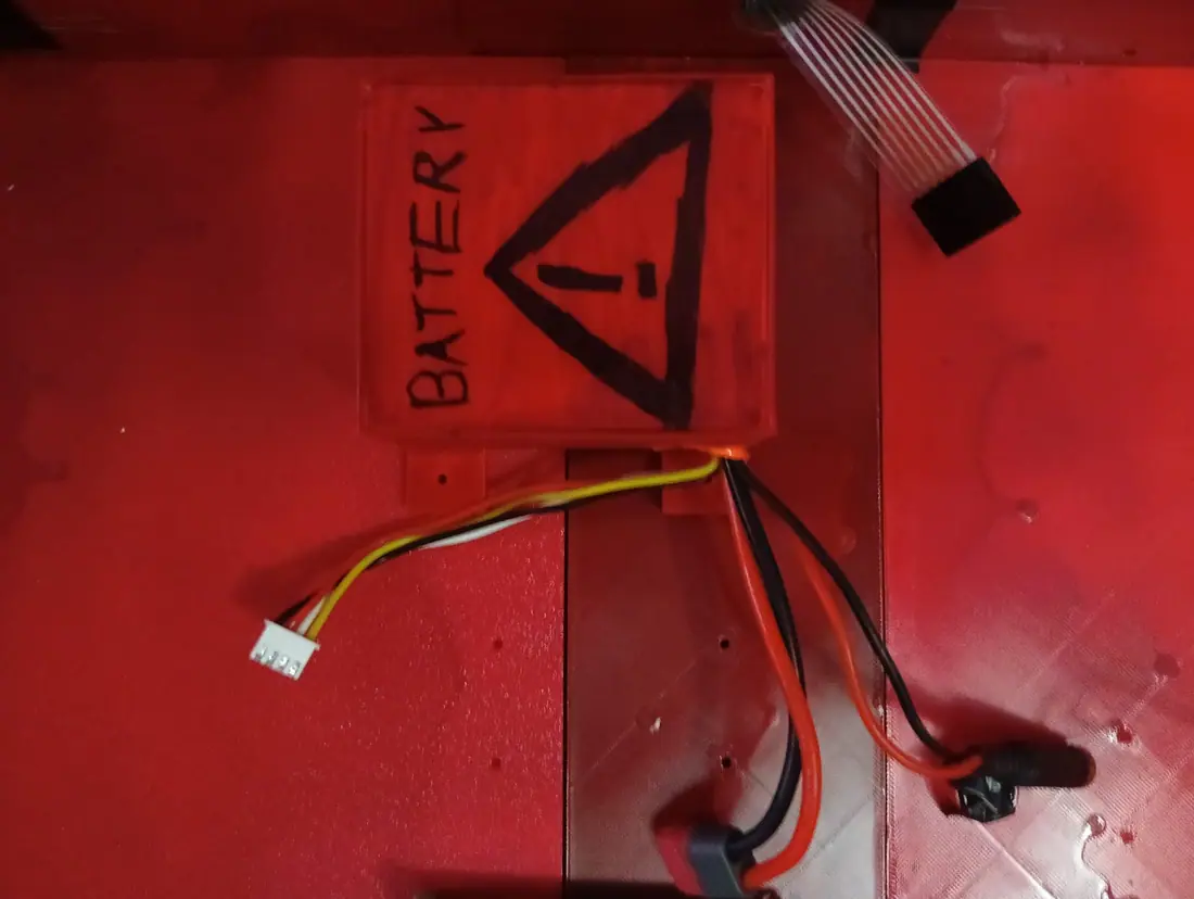
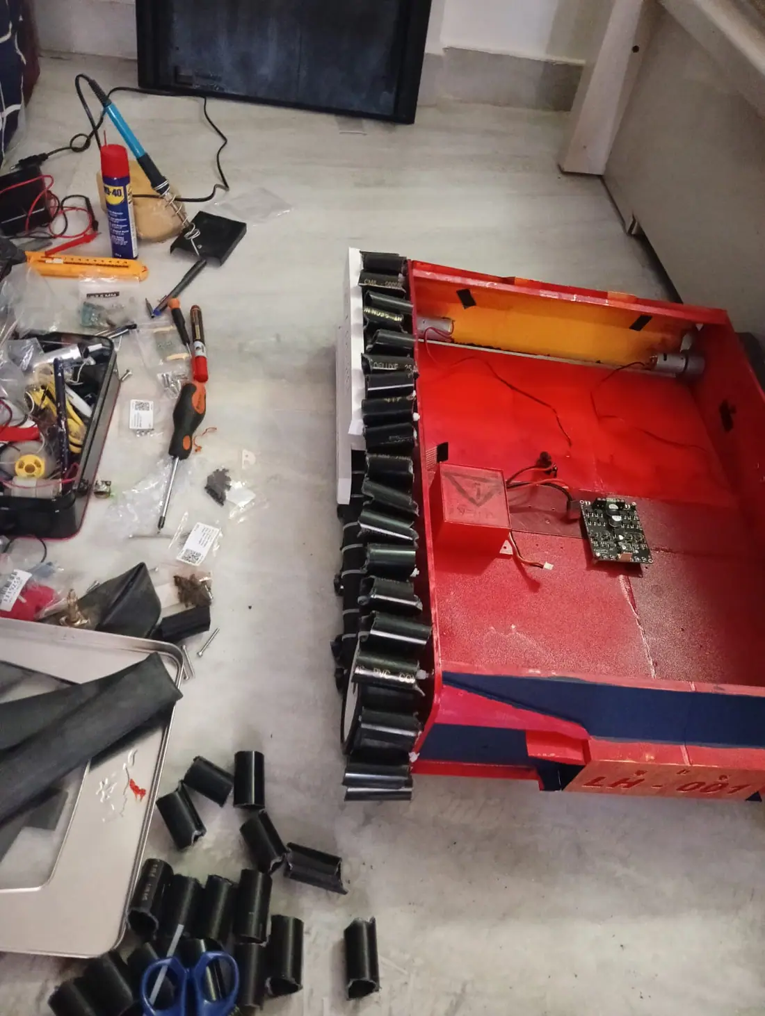
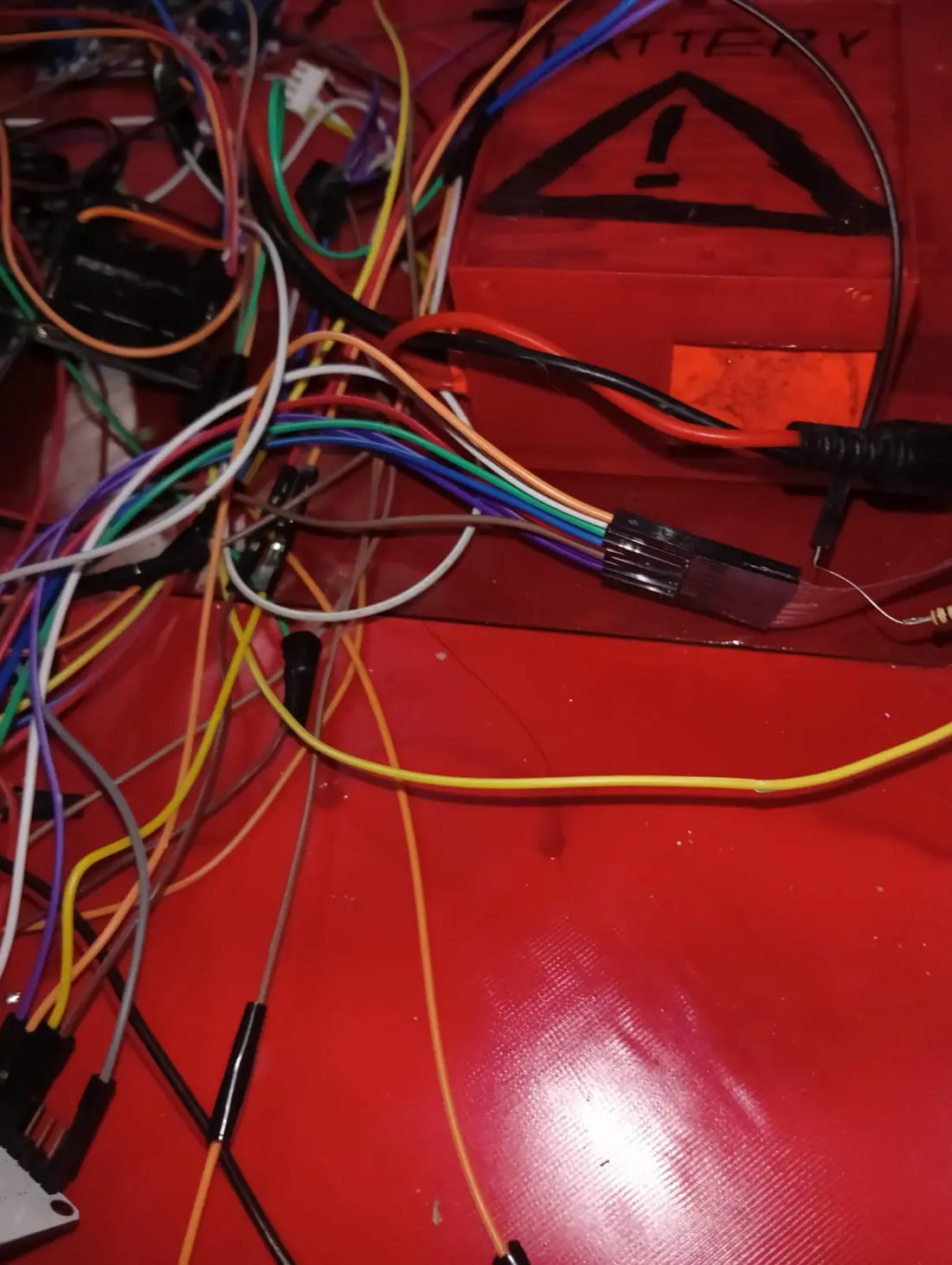
Since I spray painted the other side of the battery holder cover, I made it red using a permanent marker and added a caution battery sign. Then I took off the right track and counted the number of pipe segments I had (67) and then started placing the pipe segments on the tube 0.6 in apart (I just approximately used my thumb). I ended up with 28 pipes left for the other track which is slightly off but should still do. However, since I didn't have any power tools to cut the pipe segments, some of the segments are slightly longer and they aren't fitting in the guiderails. So I have to figure out a way to shorten those specific pieces now.

Image 1 from devlog #57: Battery Holder Design and Right TrackImage 2 from devlog #57: Battery Holder Design and Right TrackImage 3 from devlog #57: Battery Holder Design and Right Track
#58Trying to Make the Tracks Fit and Finishing other TrackAug 15, 2026

I started sawing off the excess from the pieces that didn't fit, but then I realised that that was too time consuming. So I fniished ziptying the parts for the other track, and then decided to adjust the guiderails so that that would just have a larger gap.

Image 1 from devlog #58: Trying to Make the Tracks Fit and Finishing other Track
#59Attempting to figure out the tracks (1h5mins)Aug 15, 2026

I tried to extend the space for the guiderails, which worked and the tracks weren't getting stuck on the guiderails anymore. However, the tracks are being thrown off the wheels since there isn't anything to stop it over there which I have been unsuccesfully trying to fix via a combination of zipties, pipes and anything else I can possibly think off. Also the guiderails are now pretty flimsily attached, so I will have to add a few more screws or just something to hold it in places properly.

#60More Track Fixing(1h5mins)Aug 15, 2026

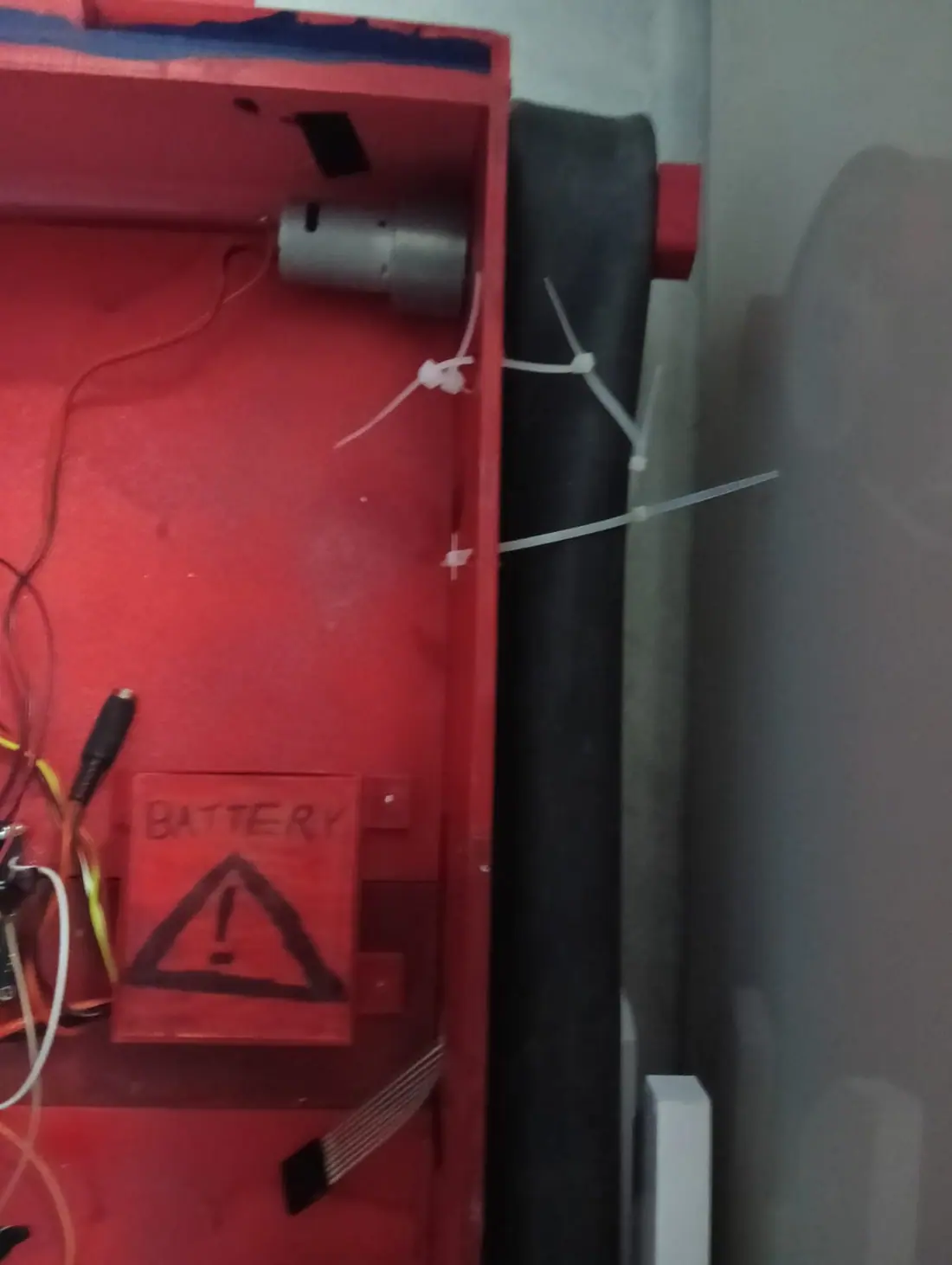
I tried so many different ways to fix the tracks, first I tried to hot glue boundaries then hot glue a pipe, then finally when that didn't work I metlocked on two attachments to the guiderails so it wouldn't detach there. Unfortunately the damn tracks just climbed the guiderails, so I melted a clear plastic sheet in half and glued that ontop as another barrier. Then after all that the tracks now no longer derail but get stuck a lot, but I'm just going to WD40 the shit out of it and hope that that + the obscene amounts of torque the motor has fixes it. I have wanted to give up so many times today, and I still absolutely want to give up on this project.

Image 1 from devlog #60: More Track Fixing(1h5mins)Image 2 from devlog #60: More Track Fixing(1h5mins)Image 3 from devlog #60: More Track Fixing(1h5mins)Image 4 from devlog #60: More Track Fixing(1h5mins)
#61Basic Electronics (1h10mins)Aug 15, 2026

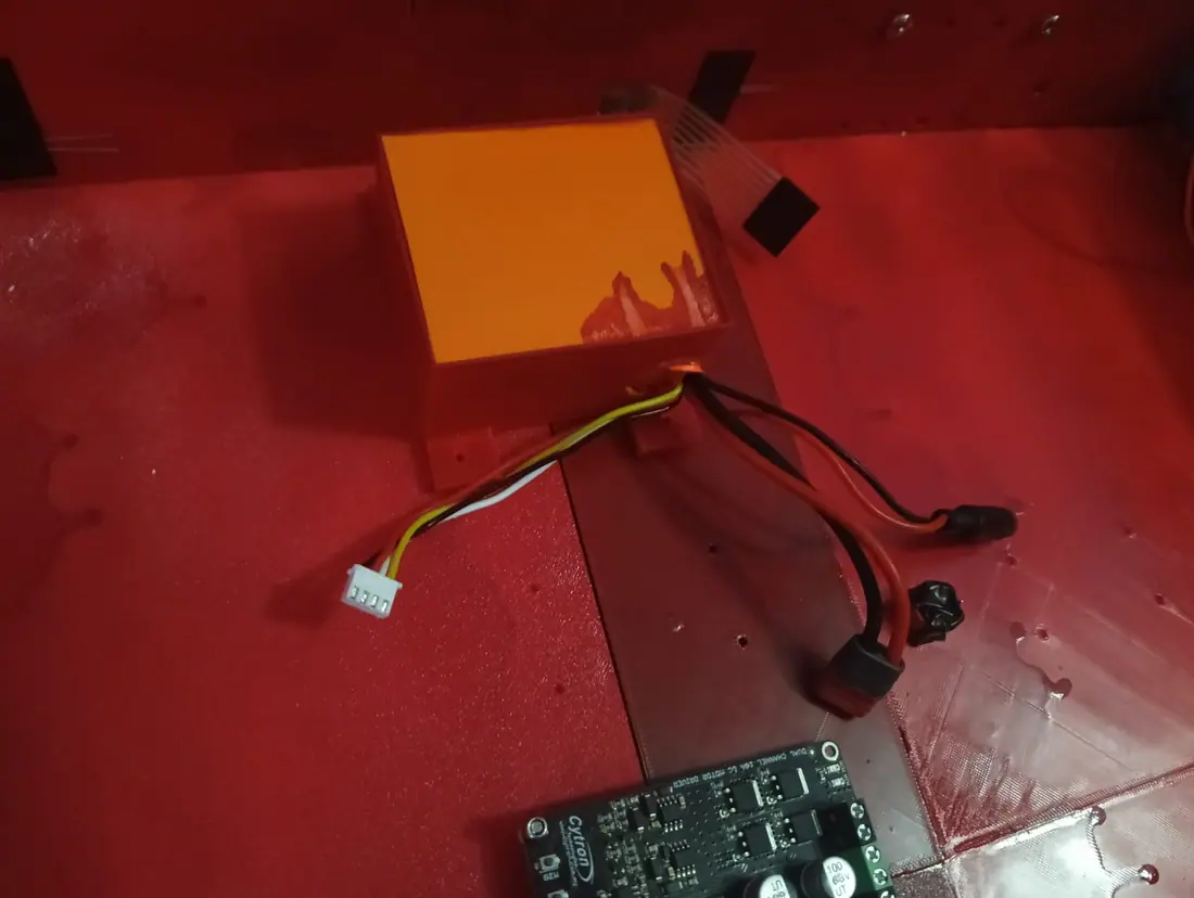
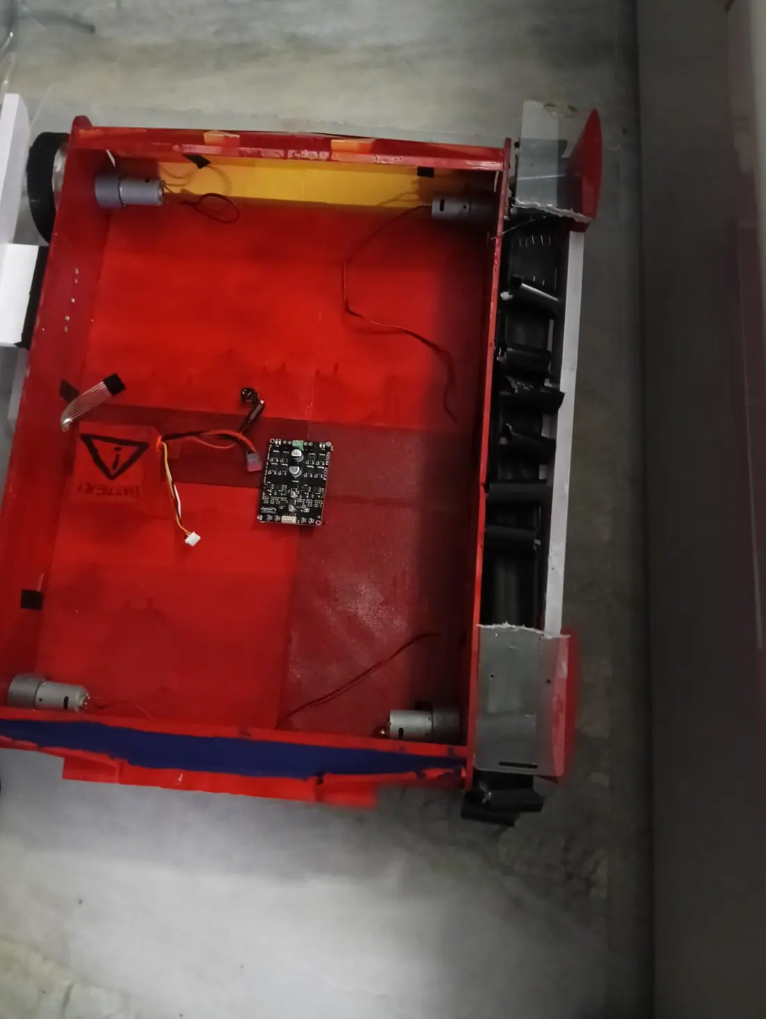
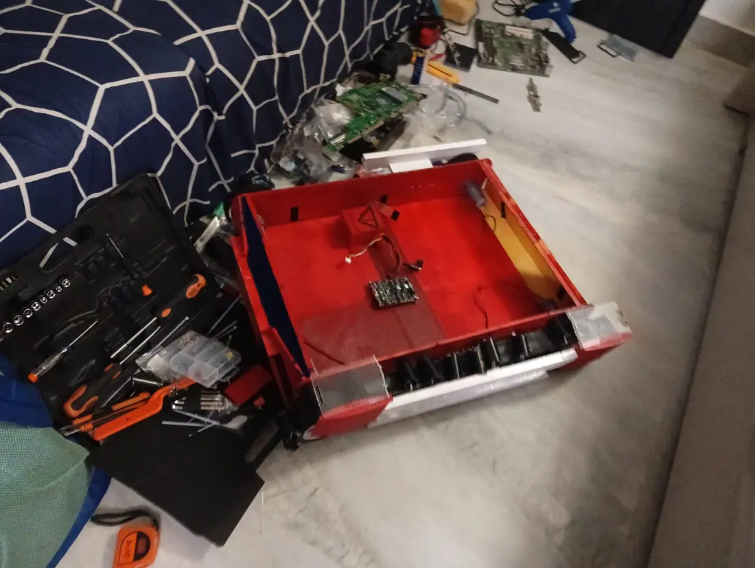
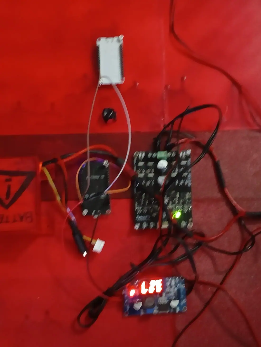
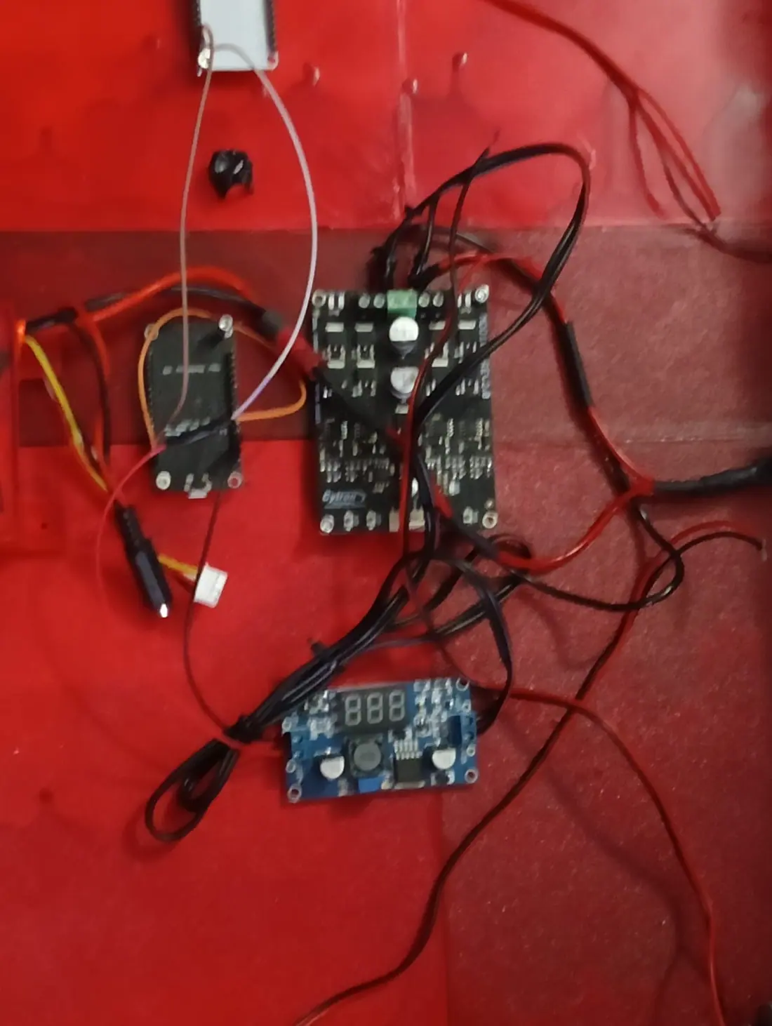
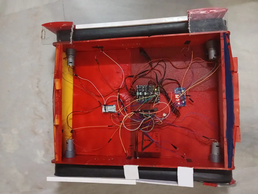
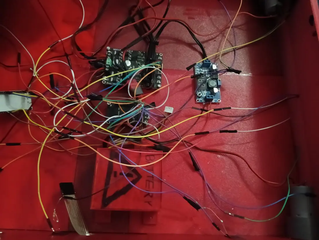
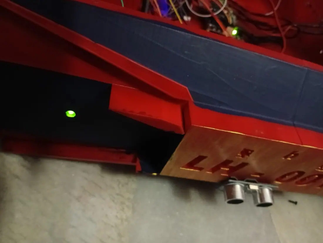
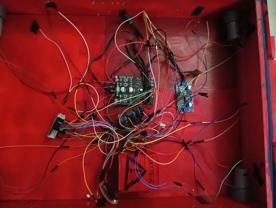
So I first put the other track on and decided that I'll figure it out after I do the electronics. I mounted the ultrasound using double-sided tape since the mounting plate just didn't print, and mounted the ESP32 and 8266 inside. Then I soldered wires together to create the 2 pathways from the battery- 1 to the motor driver(12V) and the other to the ESP(3.3V). I figured out how to setup the cool new step-down converter I got, and then I connected the ESPs to the power source and connected the grounds. And I used more double sticking tape to fix the step-down module to the chassis.

Image 1 from devlog #61: Basic Electronics (1h10mins)Image 2 from devlog #61: Basic Electronics (1h10mins)Image 3 from devlog #61: Basic Electronics (1h10mins)
#62Wiring (45mins)Aug 15, 2026

So I connected the motors to the motor driver and then used the buttons on the motor driver to test the motors and it was really cool. Then I soldered some wires to make them longer and used those to connect the motor driver to the ESP. I'm hoping all goes well with the tracks when I connect it and try to move.

Image 1 from devlog #62: Wiring (45mins)
#63Trying to Fix Tracks (1h35mins)Aug 15, 2026

So I tried so hard to fix the tracks, but that still under process. I first cut off the pvc pipes from all the tracks, maybe I'll re-add it later if I can. I melted some holes in the chassis to keep ziptie loops to hold the tracks in place, though that didn't work. I also removed the guiderails and put them back with the old, shorter screws. I added flanges to the wheels on one side to try and keep the tracks on, shortened the track length on one side and then made it longer again, fixed one of the guiderails since it broke a bit, and used a soldering iron to make a hole in the chassis to add a 3rd screw to one of the motors to try and make sure it was held firmly in place. I am really struggling to figure this out.

Image 1 from devlog #63: Trying to Fix Tracks (1h35mins)Image 2 from devlog #63: Trying to Fix Tracks (1h35mins)
#64Track fixing and resistors (1h10mins)Aug 15, 2026

So now what I did was I stuck pipe segments around the wheel between the parts that I fit previously, and added first a piece of plastic to the guiderail and when that didn't work a sheet of cut foamboard. Then after all that was done while I waited for the pipe segments to be set properly, I started soldering resistors onto the LEDS, but due to the position in the chassis and the fact that the solder just wouldn't stick it was really hard. I also removed the zipties since they weren't helping at all.

Image 1 from devlog #64: Track fixing and resistors (1h10mins)Image 2 from devlog #64: Track fixing and resistors (1h10mins)
#65Lights Camera Action (1h35mins)Aug 15, 2026

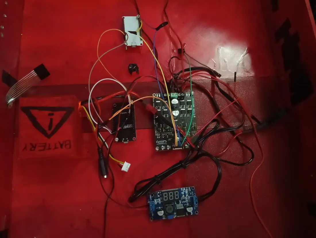
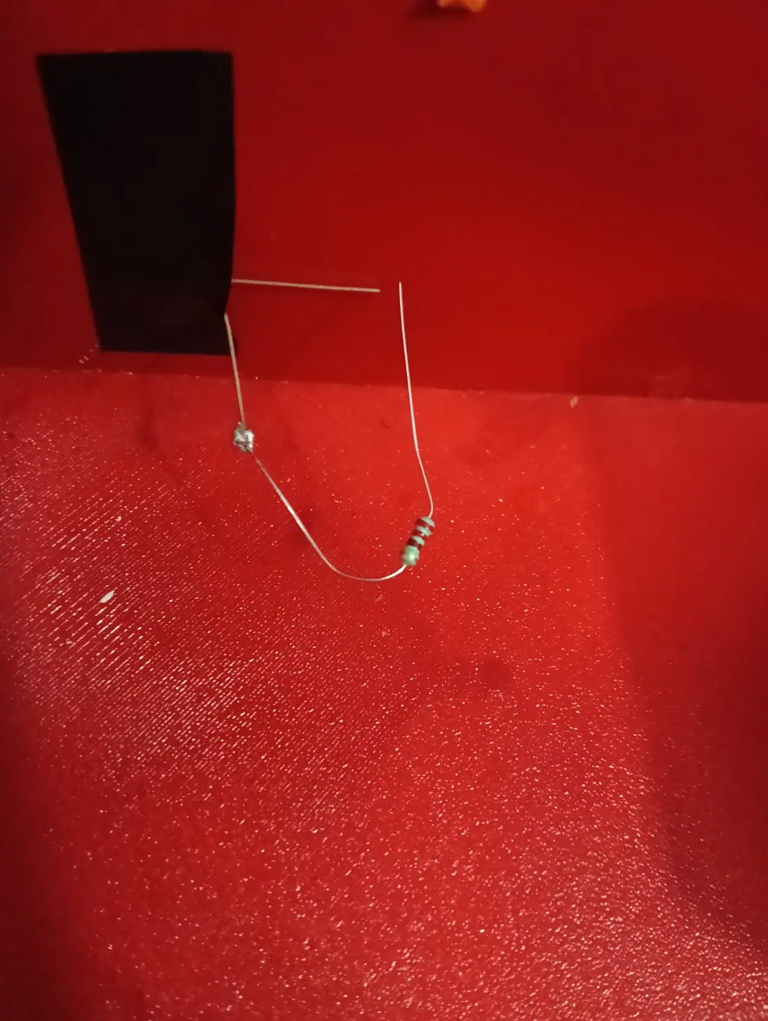
So a bit late on this devlog, but I soldered the resistors onto the leds, which proved to be difficult soldering it straight on, and I didn't have enough yellow resistors, so I had to use some green ones. I soldered together all the power wires so they all went to 1 5v pin and all the grounds together. I also made some changes to the guiderail (extended them) and managed to get the bot working at low torque (I didn't want to try using high torque yet cause I was scared it'll break). I didn't lapse the guiderail fixing though since it was really late.

Image 1 from devlog #65: Lights Camera Action (1h35mins)Image 2 from devlog #65: Lights Camera Action (1h35mins)Image 3 from devlog #65: Lights Camera Action (1h35mins)Image 4 from devlog #65: Lights Camera Action (1h35mins)
#66Fixing Leds and Wiring Ultrasonic (43mins)Aug 15, 2026

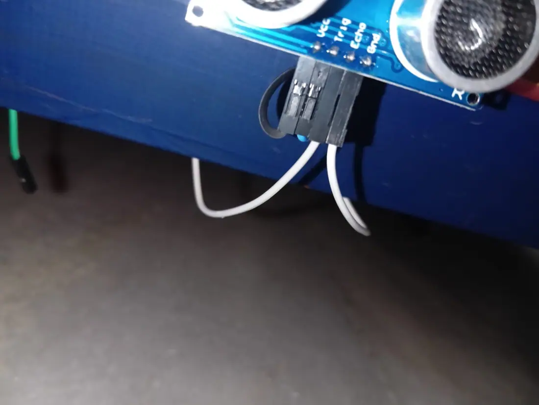
So first I realised one LED wasn't shining at all and the other was just off, so I kept testing the leds to see what was wrong and found that one had really low current draw and the other just was dead, I swapped out that LED and tried lower resistance resistors but the leds were still really dim. I realised that the current was automatically being limited in the circuit so I just connected those LEDS without the resistors. Then what I did next was I took out the electronic schematic of the bot on my tablet and connected the ultrasonic sensor to the esp32, linking multiple jumper wires together to get a wire that was long enough.

Image 1 from devlog #66: Fixing Leds and Wiring Ultrasonic (43mins)Image 2 from devlog #66: Fixing Leds and Wiring Ultrasonic (43mins)Image 3 from devlog #66: Fixing Leds and Wiring Ultrasonic (43mins)Image 4 from devlog #66: Fixing Leds and Wiring Ultrasonic (43mins)
#67Wiring RFID and NumpadAug 15, 2026

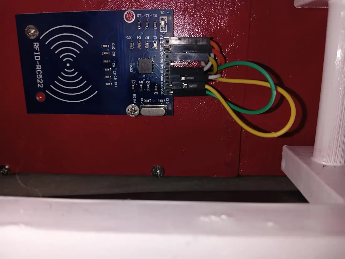
I connected the wires to the esps for the RFID scanner and number pad and also accidentally burned myself on my soldering iron.

Image 1 from devlog #67: Wiring RFID and NumpadImage 2 from devlog #67: Wiring RFID and NumpadImage 3 from devlog #67: Wiring RFID and Numpad
#68★Finishing up wiring,fixning guiderail and hella debuggingAug 16, 2026

So I worked on connecting the LCDs and then the esps together and I fixed a guiderail that broke. Also I spent about 5 hours debugging none of which I could actually log due to the nature of it. In my debugging I fixed so many issues like: the bots 5vs dont work since the buck is set to 3.3 so I had to change the entire power schematic, esps rx was connected to rx, matrix mapping for keypad was wrong, pins were connected to incompatible pins and a lot more. My 5 hours of debugging have left me with only the ultrasonic sensor not working.

#69Finishing up the Physical BuildAug 17, 2026

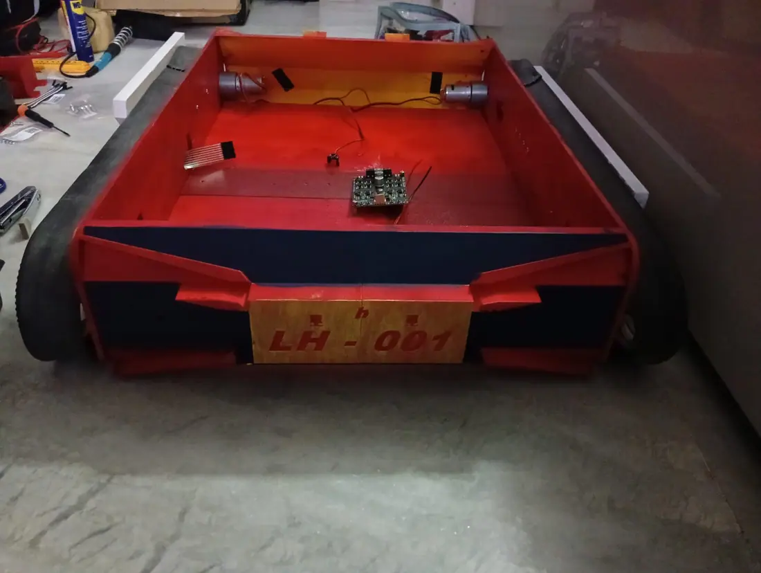
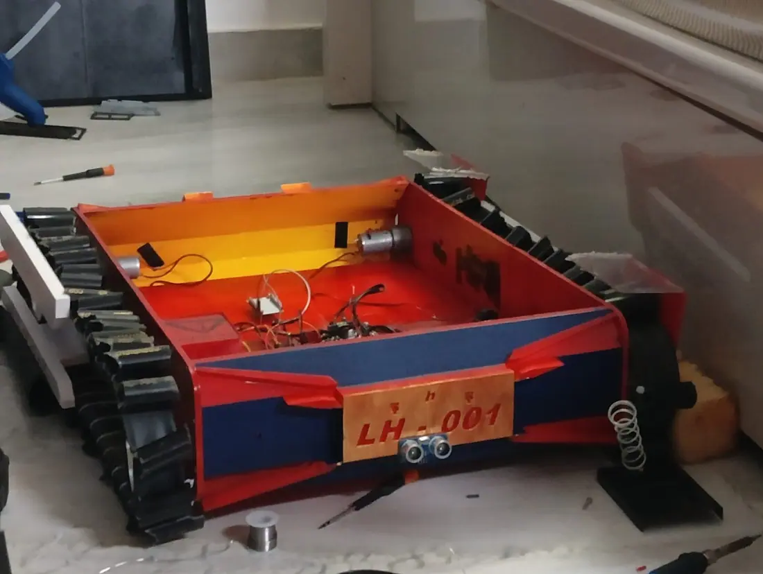
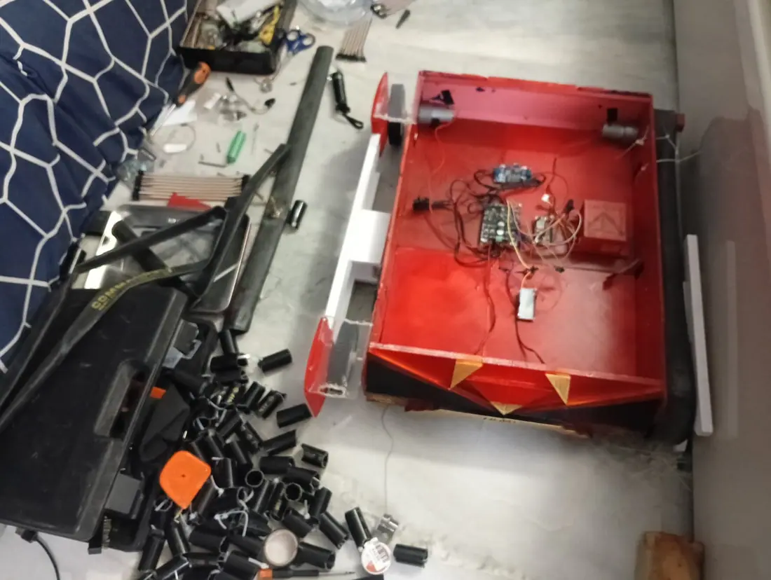
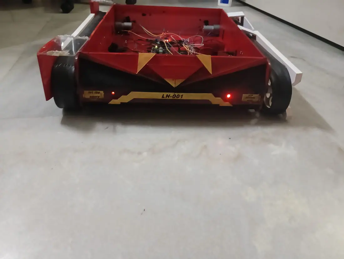
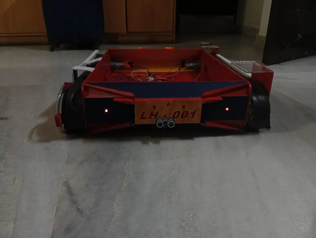
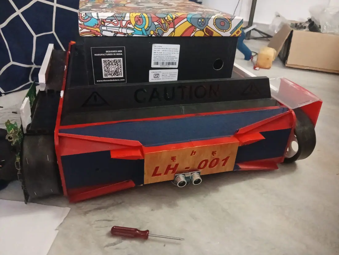
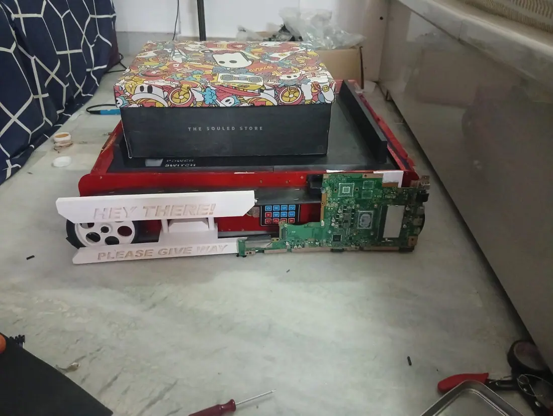
So I began by fixing up the wiring since some of the leds needed resistors soldered on and the back leds needed to have longer wires so the back could open. I screwed down the ESPS since I had unscrewed them to work on them. I went to mount the top plate and realised the power button doesn't reach the slot and I don't have heavy duty cables to extend the wires so I decided for this version of the bot it would have to be powered on by opening the back, and it can also be charged that way. I then mounted on a shoebox to the roof since that was the only box I had available, and then started screwing in the top plate. The back plate movement is really hindered by the top plate so I left one screw undone so the top plate can lower a bit when the backplate opens allowing about 4 inches of a gap when opened. I also fixed a part of one of the guiderails that had broken off. The bot has been misdesigned and the front plate is slightly too long and so it can't climb stairs without that redesign, which I will do in the V2 of the bot, so this version doesn't have stair climbing capabilities. This is the conclusion of the irl build of the bot : D.

Image 1 from devlog #69: Finishing up the Physical BuildImage 2 from devlog #69: Finishing up the Physical Build
#70Added details to the RepoAug 19, 2026 · 45m tracked

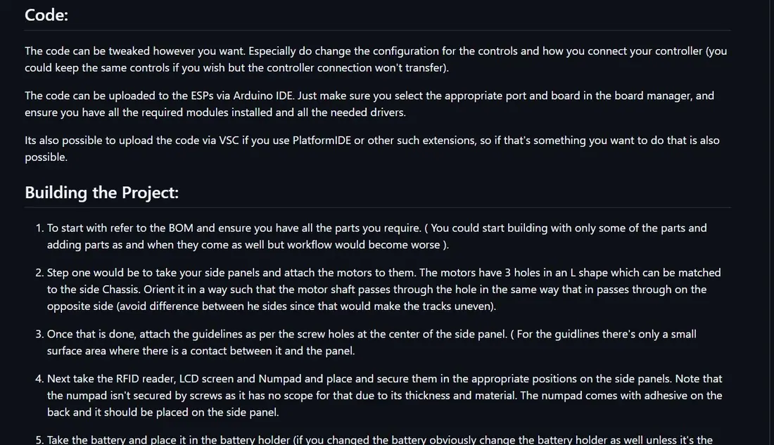
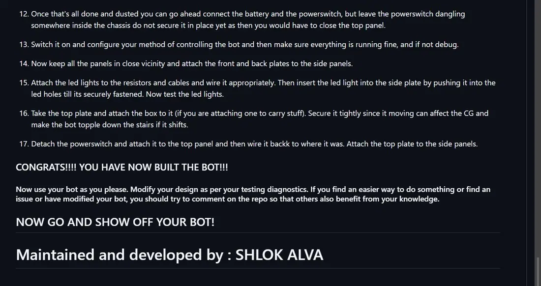
So for some of the finishing touches on the project I added build instructions and photos to the git repo and then added the code files to the repo as well. I added some enhancements to the appearance of the readme as well by adding photos into the build instructions of the code,bom,hardware build etc. I also included the demo video link.

Image 1 from devlog #70: Added details to the RepoImage 2 from devlog #70: Added details to the Repo

← Back To Portfolio

Made with AI. This site was built with AI assistance (Claude, by Anthropic). The devlog entries, photos and results are my own work.